Charge pump

a technology of pump and discharge pump, applied in the direction of electrical equipment, pulse automatic control, etc., can solve the problem of more jitters in the system

Inactive Publication Date: 2005-04-05
IBM CORP
View PDF1 Cites 7 Cited by
  • Summary
  • Abstract
  • Description
  • Claims
  • Application Information

AI Technical Summary

Benefits of technology

The present invention provides a structure comprising (a) charge pump receiving a first charge pump input signal and a second charge pump input signal, the charge pump including a sourcing current path which includes a sourcing current control gate; and (b) a charge pump current controller receiving as inputs the first and second charge pump input signals, wherein the charge pump current, controller is configured to generate a sourcing current control signal to the sourcing current control gate in response to the first and second charge pump input signals being at opposite levels, and wherein the sourcing current control gate is configured to change its current in response to the sourcing current control signal being generated.

Problems solved by technology

It may occur that even when the phase difference between the two inputs of the conventional charge pump is small, the VCO is driven hard causing more jitters in the system.

Method used


Image

  • Charge pump
  • Charge pump
  • Charge pump

Examples


Embodiment Construction

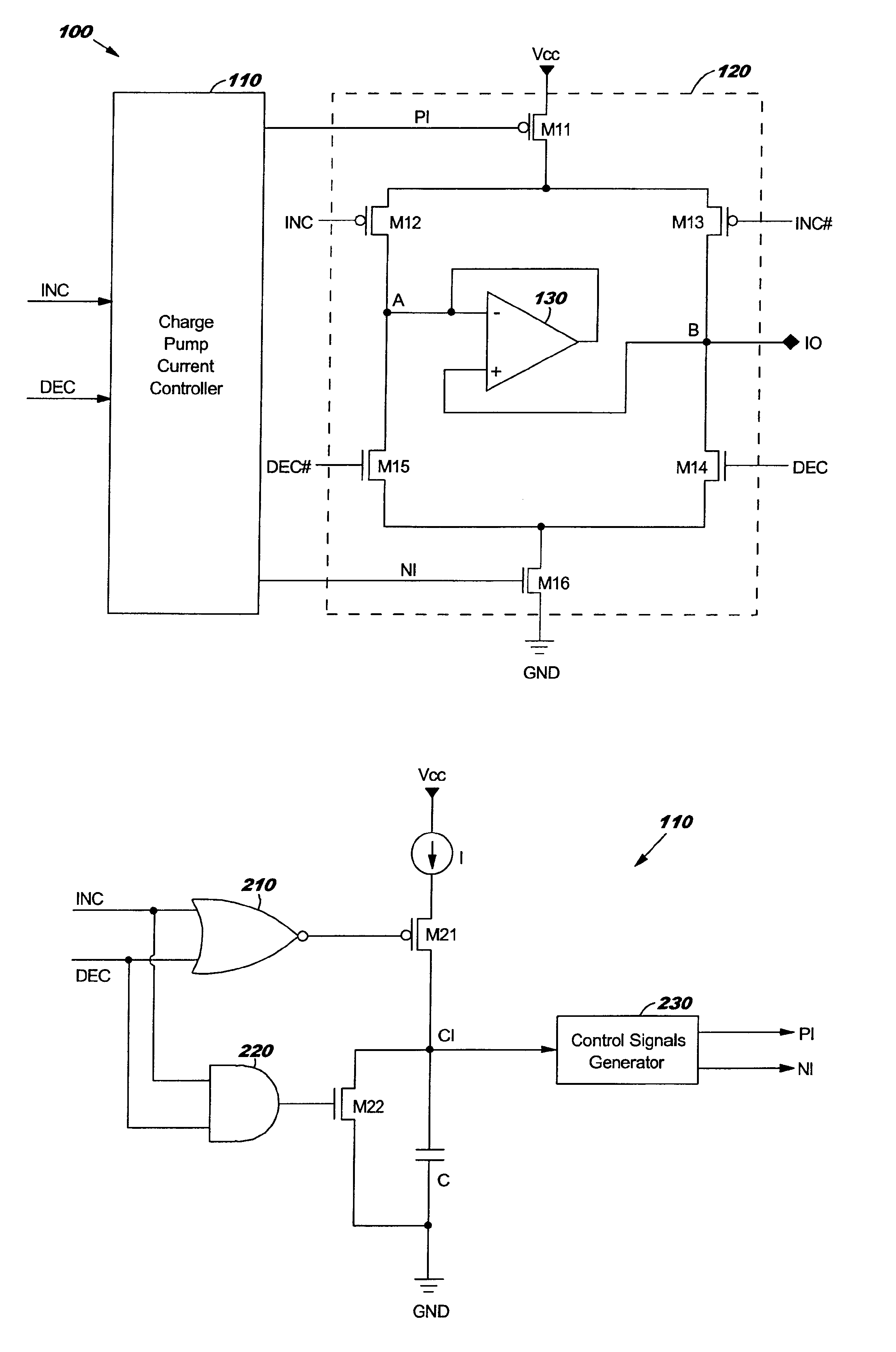
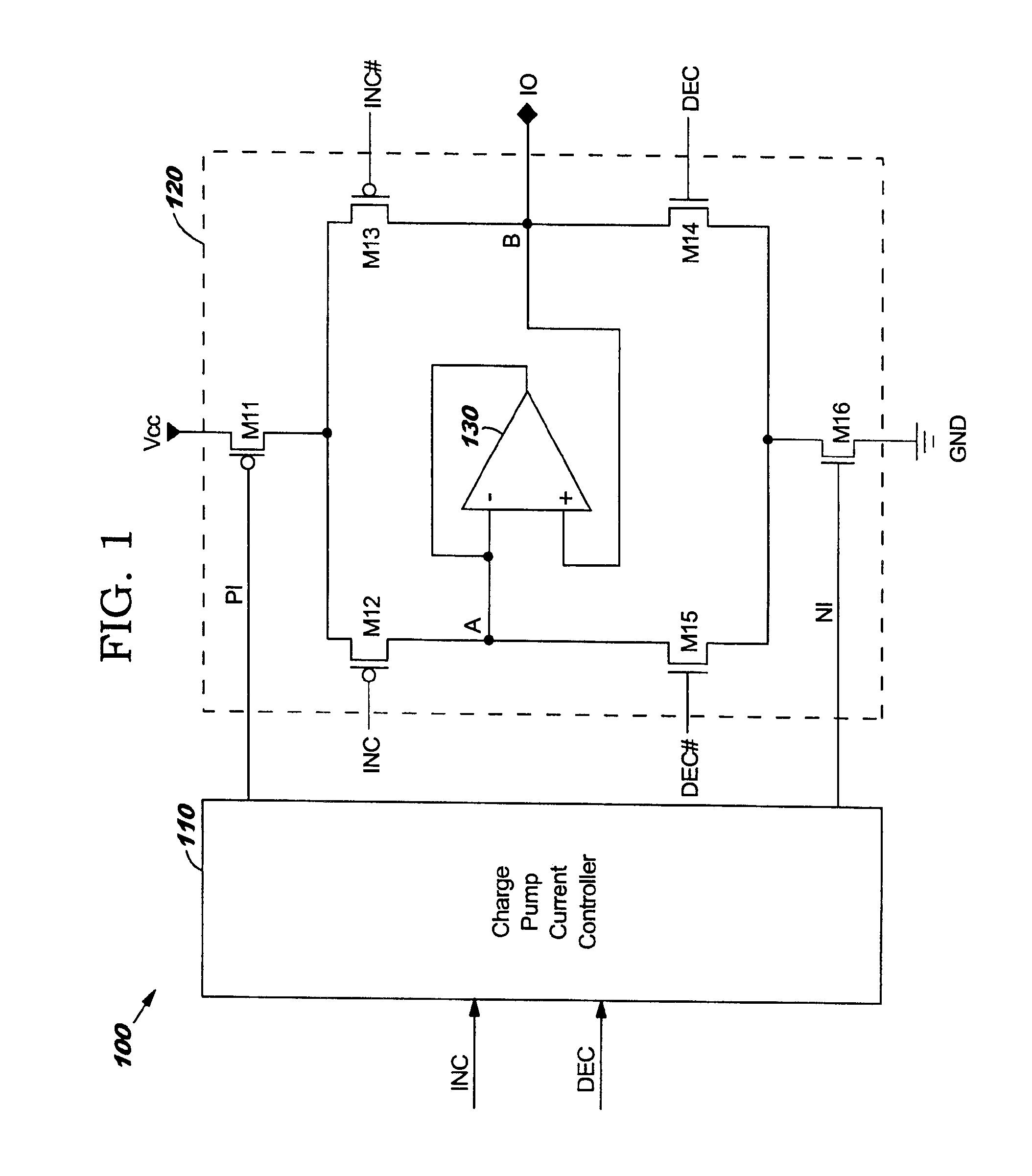
FIG. 1 illustrates a structure 100 comprising a charge pump current controller 110 and a charge pump 120, in accordance with embodiments of the present invention. Illustratively, the charge pump 120 comprises an operational amplifier (op-amp) 130, P-channel transistors M11, M12, and M13, and N-channel transistors M14, M15, and M16.

The transistors M11, M12, M15, and M16 are electrically coupled together in series between VCC and ground. The transistors M11, M13, M14, and M16 are electrically coupled together in series between VCC and ground. In effect, the pair transistors M12 and M15 and the pair transistor M13 and M14 are electrically coupled together in parallel and in series with the transistors M11 and M16 between VCC and ground.

The transistors M12 and M15 have a common node A. Similarly, the transistors M13 and M14 have a common node B. The op-amp 130, in negative feed back configuration, is electrically coupled between node A and node B. As a result, the voltage levels at node...


PUM


Abstract

A structure comprising a charge pump and a charge pump current controller electrically coupled together, and a method for operating the structure. The charge pump comprises a sourcing current control gate on the charge pump's sourcing current path, and a sinking current control gate on the charge pump's sinking current path. The longer the two inputs of the charge pump are at the opposite levels, the more the charge pump current controller causes the sourcing and sinking current control gates to increase the sourcing and sinking currents flowing through the sourcing and sinking current paths, respectively.

Description

BACKGROUND OF INVENTION1. Technical FieldThe present invention relates to charge pumps, and more specifically, to a charge pump that has its sinking and sourcing currents proportional to the phase difference between its two inputs.2. Related ArtIn general, a conventional charge pump has two inputs and one output. The conventional charge pump is configured such that when its two inputs are out of phase, there is either a sinking current (flowing into the charge pump) or a sourcing current (flowing out of the charge pump) through its output. However, these sinking and sourcing currents in the conventional charge pump do not depend on whether the phase difference between its two inputs is large or small. Assume that the conventional charge pump is electrically coupled to a VCO (Voltage-Controlled Oscillator). It may occur that even when the phase difference between the two inputs of the conventional charge pump is small, the VCO is driven hard causing more jitters in the system.It is t...

Claims


Application Information

Patent Timeline
Patent Type & Authority Patents(United States)
IPC IPC(8): H03L7/06H03L7/089H03L7/107
CPCH03L7/0898H03L7/1072H03L7/107
Inventor KELKAR, RAMMALLADI, ANJALI R.
Owner IBM CORP
Why Eureka
Try Eureka