
Power distribution panel with modular elements

a technology of power distribution panel and modular elements, which is applied in the direction of substation/switching arrangement casing, emergency protective arrangement for limiting excess voltage/current, and arrangement responsive to excess voltage, etc., can solve the problems of significant retooling time and cost, limited type and arrangement of components, and difficulty in assembly of circuit elements, etc., to achieve the effect of increasing the ease of producing variable product lines or customized circuit panels, and faster delivery to customers

Inactive Publication Date: 2005-03-29
COMMSCOPE TECH LLC
View PDF6 Cites 30 Cited by
  • Summary
  • Abstract
  • Description
  • Claims
  • Application Information

AI Technical Summary

Benefits of technology

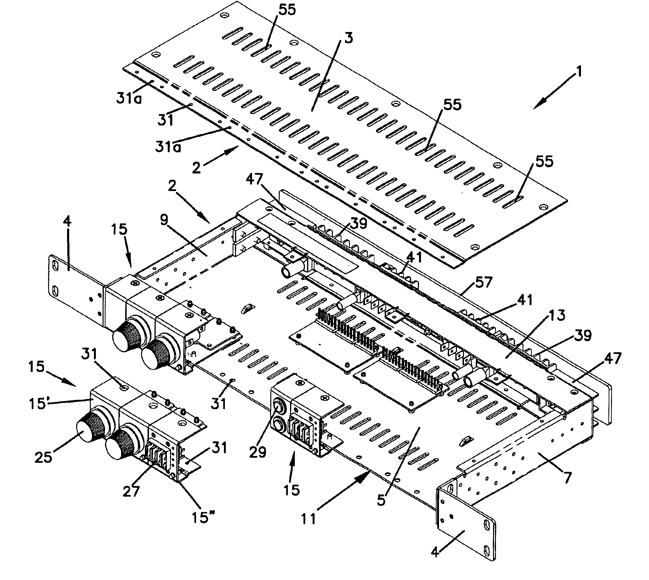
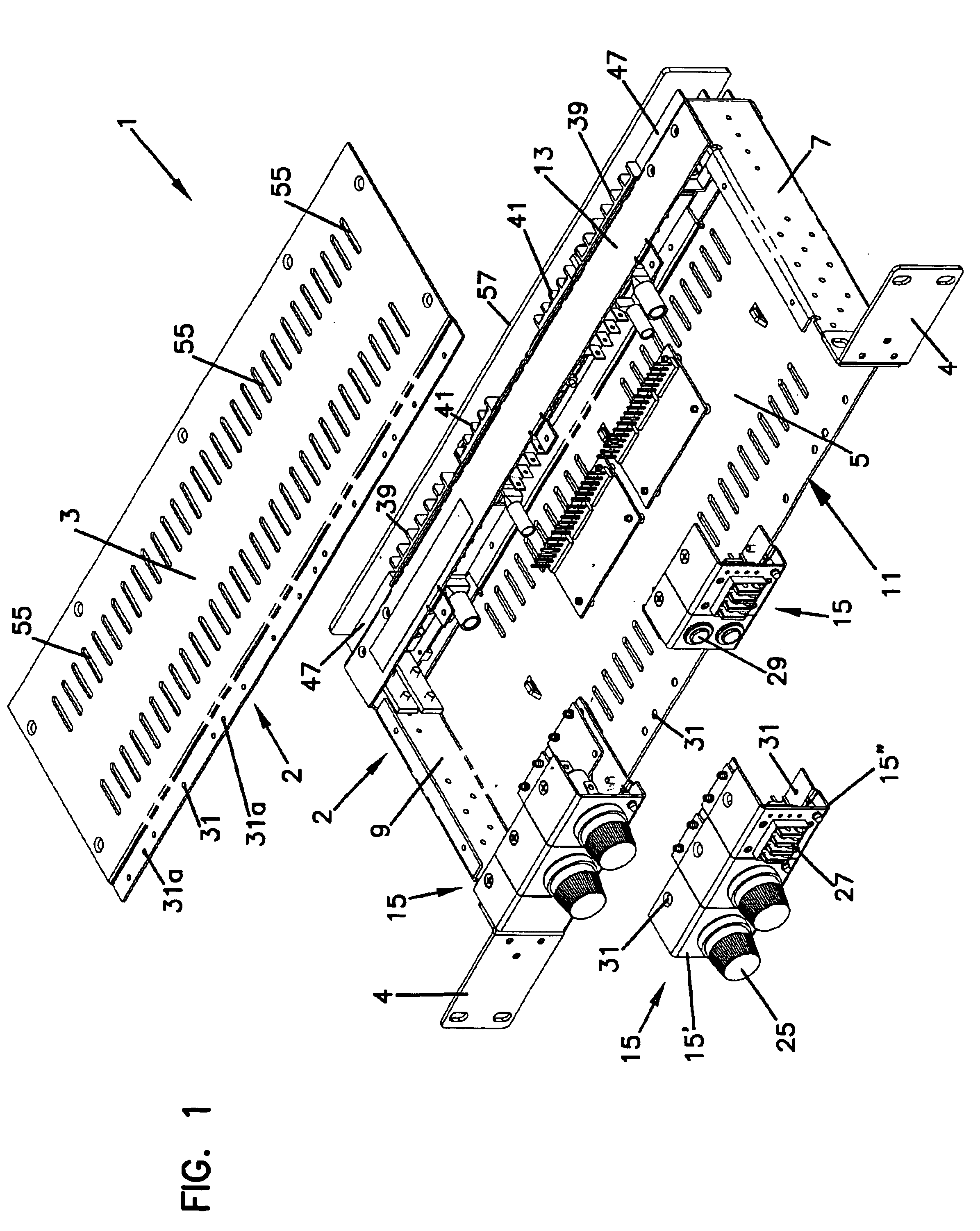
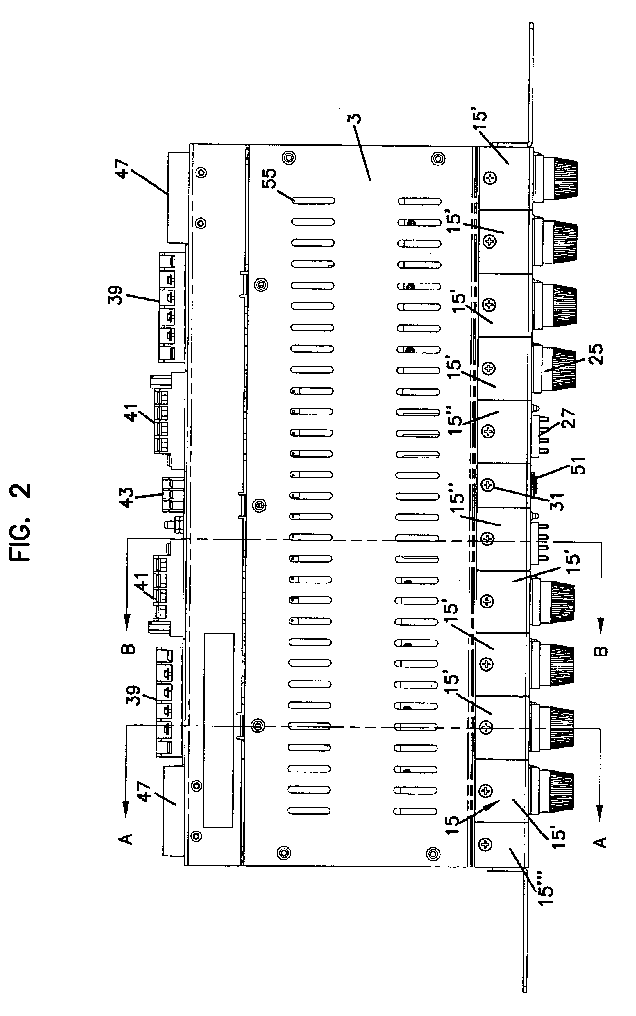
The present invention is an improved circuit panel such as a power distribution panel constructed with circuit element modules. The circuit element modules eliminate the need for punching patterns of specially shaped holes into a front and / or back panel of the housing structure for each element. The circuit elements are disposed on modular members of standardized dimensions which allow the elements to be coupled to the housing structure in one of a variety of selected configurations without the need to customize a hole pattern in a front panel of the housing structure. Eliminating the discrete hole punching increases the ease of producing variable product line or customized circuit panels and results in quicker delivery to the customer.

Problems solved by technology

These prior circuit panels are fixed in that once the holes are formed in the housing, the type and arrangement of the components is limited.
Significant retooling time and costs are involved for offering different fixed panels.
Assembly of the circuit elements is also difficult when the elements are inserted through the holes.

Method used


Image

  • Power distribution panel with modular elements
  • Power distribution panel with modular elements
  • Power distribution panel with modular elements

Examples


Embodiment Construction

A power distribution panel is a circuit panel which channels power from a supply line input power to a number of different pieces of equipment. Therefore, a power distribution panel typically has one or more power input connections and an array of output connections to which the pieces of equipment to be supplied with power are connected. The typical power distribution panel also comprises an array of fuse locations, normally one fuse location for each output connection. Alternatively, or in combination, circuit protection may be provided by circuit breakers. This specification and accompanying drawings relate to preferred embodiments of a power distribution panel primarily with fuse modules but it is to be understood that the present invention is applicable to other types of circuit panels using other circuit element modules such as circuit breaker modules, other circuit protection modules, or other circuit element modules with different functions altogether.

As shown in the preferr...


PUM


Abstract

A power distribution panel having circuit elements such as KTK and GMT fuses removably mounted to a unit housing by means of module members, thereby allowing for ease of customization of the circuit elements of the power distribution panel.

Description

FIELD OF THE INVENTIONThe present invention relates to a power distribution panel with circuit element modules.BACKGROUND OF THE INVENTIONElectrical circuit panels such as power distribution panels typically include a number of different circuit elements such as fuse holders and fuses, circuit breakers, input and output connectors, and alarm signal LEDs. For safety and other reasons, the electrical circuits of power distribution panels are enclosed within a housing structure. Therefore, the circuit elements listed above have typically been inserted into holes which have been pre-cut or pre-punched into the housing structure, usually on a front or back panel of the housing structure. These prior circuit panels are fixed in that once the holes are formed in the housing, the type and arrangement of the components is limited.In order to manufacture different fixed circuit panels of the prior systems, a circuit panel manufacturer would punch out different patterns of holes in the front o...

Claims


Application Information

Patent Timeline
Patent Type & Authority Patents(United States)
IPC IPC(8): H02B1/015H02B1/04
CPCH02B1/34H02B1/04
Inventor SCHOMAKER, DAVID E.ARROYO GONZALEZ, CARLOSHERNANDEZ, DELFINOSANCHEZ AGUILAR, LUIS MANUELDELGADO GUEVARA, NARCISOMORA CURIEL, CELSA
Owner COMMSCOPE TECH LLC
Learn More