
Single-ended-to-differential converter with common-mode voltage control

a technology of voltage control and single-ended to differential converter, which is applied in the direction of amplitude demodulation, amplifiers with min 3 electrodes or 2 pn junctions, instruments, etc., can solve the problems of difficult to fit this approach within the voltage head-room constraints of is not well suited to low voltage power supplies, etc., to achieve the effect of increasing performan

Inactive Publication Date: 2005-03-29
QUALCOMM INC
View PDF9 Cites 63 Cited by
  • Summary
  • Abstract
  • Description
  • Claims
  • Application Information

AI Technical Summary

Benefits of technology

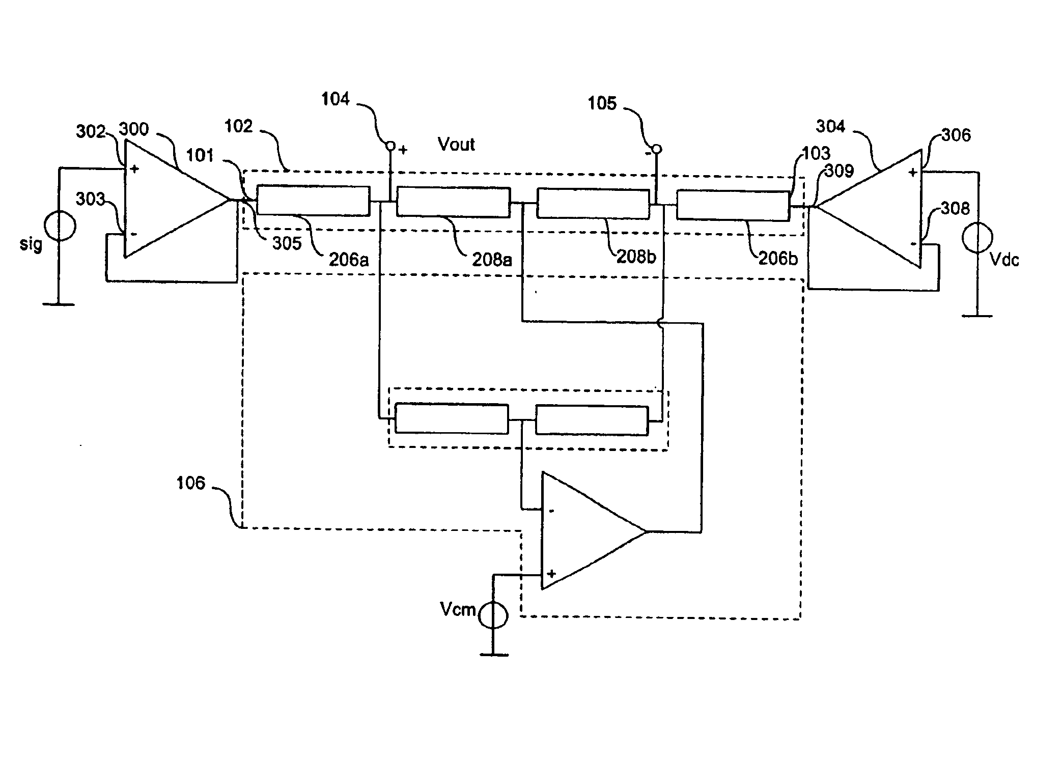
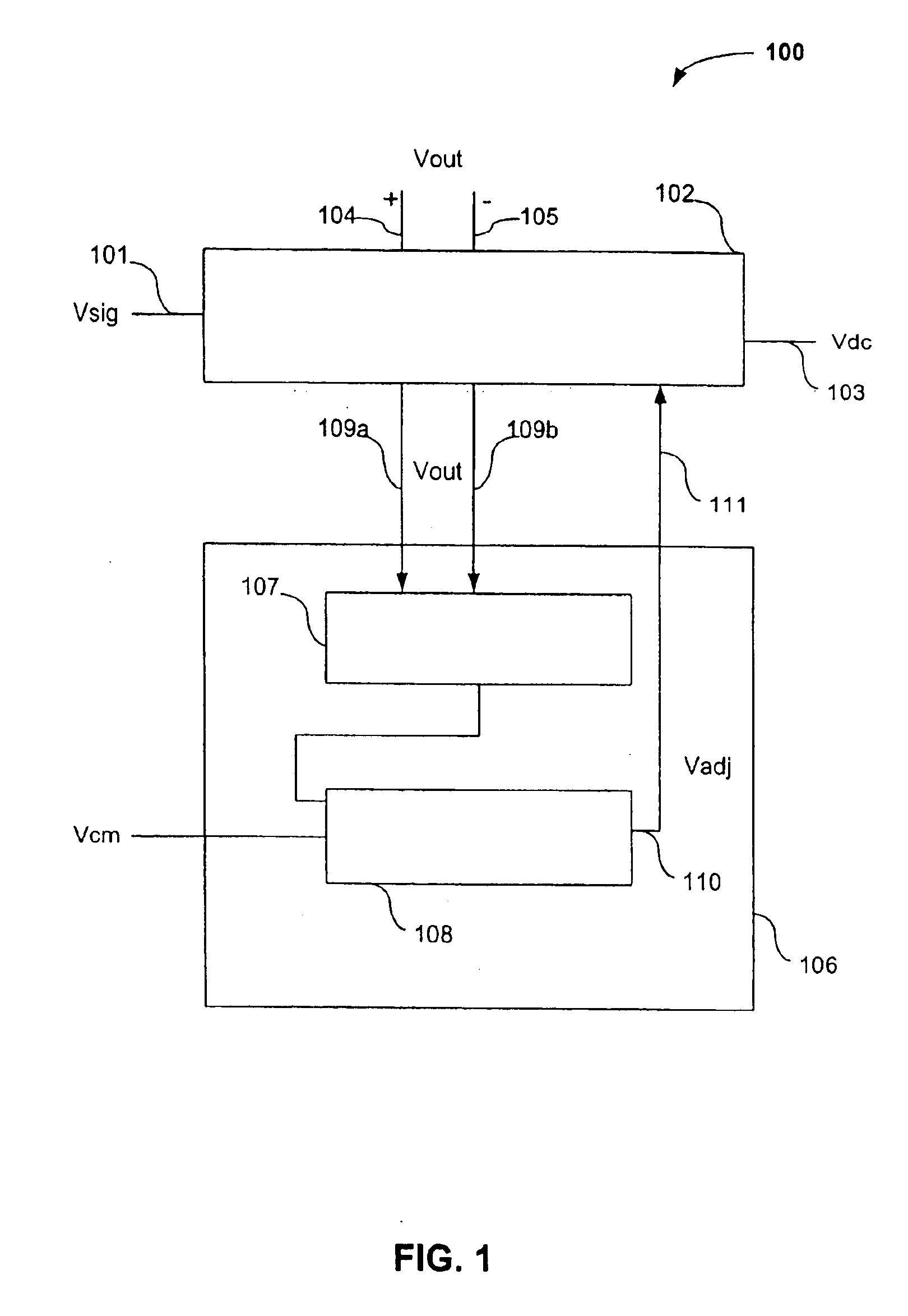
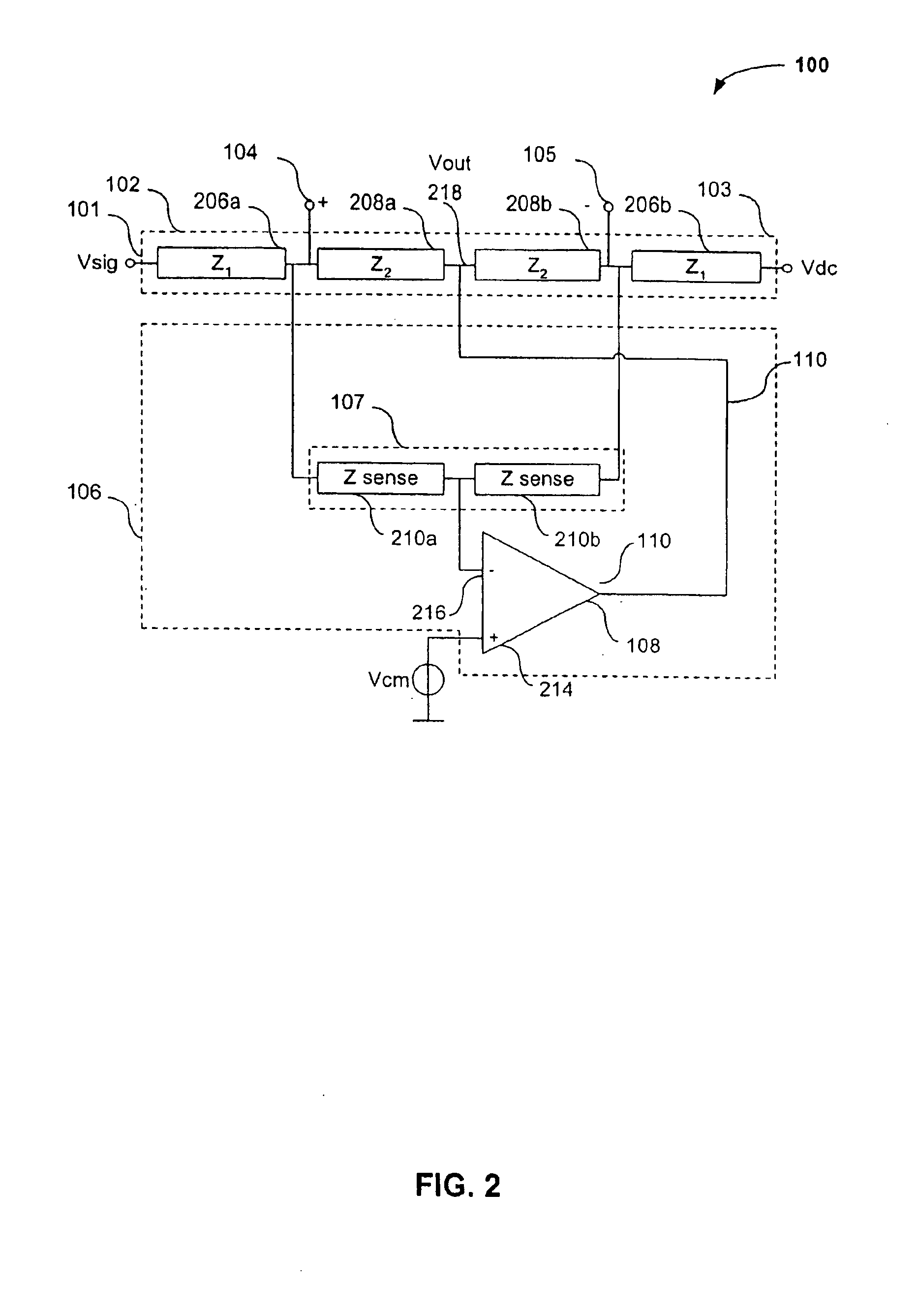
Features and advantages of the present invention include the ability to beneficially combine the functions of a low power single-ended to differential converter and an attenuator on a single IC. This approach increases the performance and provides additional space on the IC for incorporation of added functions. Additional advantages of the present invention are the ability to provide single-ended to differential conversion in a manner that fits within the voltage head-room constraints of low voltage power supplies and a provision for controlling common-mode voltage in an efficient manner.

Problems solved by technology

One deficiency with this approach is that it's not well suited for low voltage power supplies.
More specifically, it's difficult to fit this approach within the voltage head-room constraints of low voltage power supplies.
However, when providing one side of a degenerate differential pair with a relatively large signal, while at the same time, leaving the other side at a constant voltage, its extremely difficult to achieve acceptable linearity.
Although numerous traditional techniques exist to convert single-ended signals into differential signals, low voltage power supplies often do not provide adequate voltage head-room to accommodate efficient use of these traditional techniques.

Method used


Image

  • Single-ended-to-differential converter with common-mode voltage control
  • Single-ended-to-differential converter with common-mode voltage control
  • Single-ended-to-differential converter with common-mode voltage control

Examples


Embodiment Construction

The following detailed description of the present invention refers to the accompanying drawings that illustrate exemplary embodiments consistent with this invention. Other embodiments are possible, and modifications may be made to the embodiments within the spirit and scope of the invention. Therefore, the following detailed description is not meant to limit the invention. Rather, the scope of the invention is defined by the appended claims.

It would be apparent to one of skill in the art that the present invention, as described below, may be implemented in many different embodiments of hardware, software, firmware, and / or the entities illustrated in the figures. Any actual software code with specialized controlled hardware to implement the present invention is not limiting of the present invention. Thus, the operation and behavior of the present invention will be described with the understanding that modifications and variations of the embodiments are possible, given the level of de...


PUM


Abstract

Provided is a circuit to perform single-ended to differential conversion while providing common-mode voltage control. The circuit includes a converter to convert a single-ended signal to a differential signal and a stabilizing circuit adapted to receive the differential signal. The stabilizing circuit includes a sensor configured to sense a common-mode voltage level of the differential signal and a comparator having an output port coupled to the converter. The comparator is configured to compare the differential signal common-mode voltage level with a reference signal common-mode voltage level and produce an adjusting signal based upon the comparison. The adjusting signal is applied to the converter via the output port and is operative to adjust a subsequent common-mode voltage level of the differential signal.

Description

BACKGROUND OF THE INVENTION1. Field of the InventionThe present invention relates to single-ended to differential converters. More particularly, the present invention relates to a circuit technique to perform attenuation and single-ended to differential conversion with common-mode voltage control on a single integrated circuit (IC).2. Background ArtAdvances in electronic device packaging provide electronic system designers with the ability to include an increased number of functions on a single IC. Such ICs are particularly well suited for low supply voltage applications, especially those ICs that can accommodate processing of analog signals. Thus, by combining numerous functions on a single IC, electronic system designers are able to realize tremendous savings in power consumption and space. Even greater functional advantages can be realized through the selection of particular signal processing techniques to be used on these ICs.For example, in the case of analog signals on single ...

Claims


Application Information

Patent Timeline
IPC IPC(8): H03H11/02H03H11/32
CPCH03H11/32
Inventor MULDER, JANLUGTHART, MARCELLIN, CHI-HUNG
Owner QUALCOMM INC
Learn More