
Method and apparatus for converting power

a technology of power converter and power converter device, which is applied in the direction of instruments, measurement devices, and antennas, can solve the problems of inability to reduce the output inability to meet the requirements of the power converter device, so as to reduce the complexity of the controller

Inactive Publication Date: 2005-03-29
RAYTHEON CO
View PDF19 Cites 24 Cited by
  • Summary
  • Abstract
  • Description
  • Claims
  • Application Information

AI Technical Summary

Benefits of technology

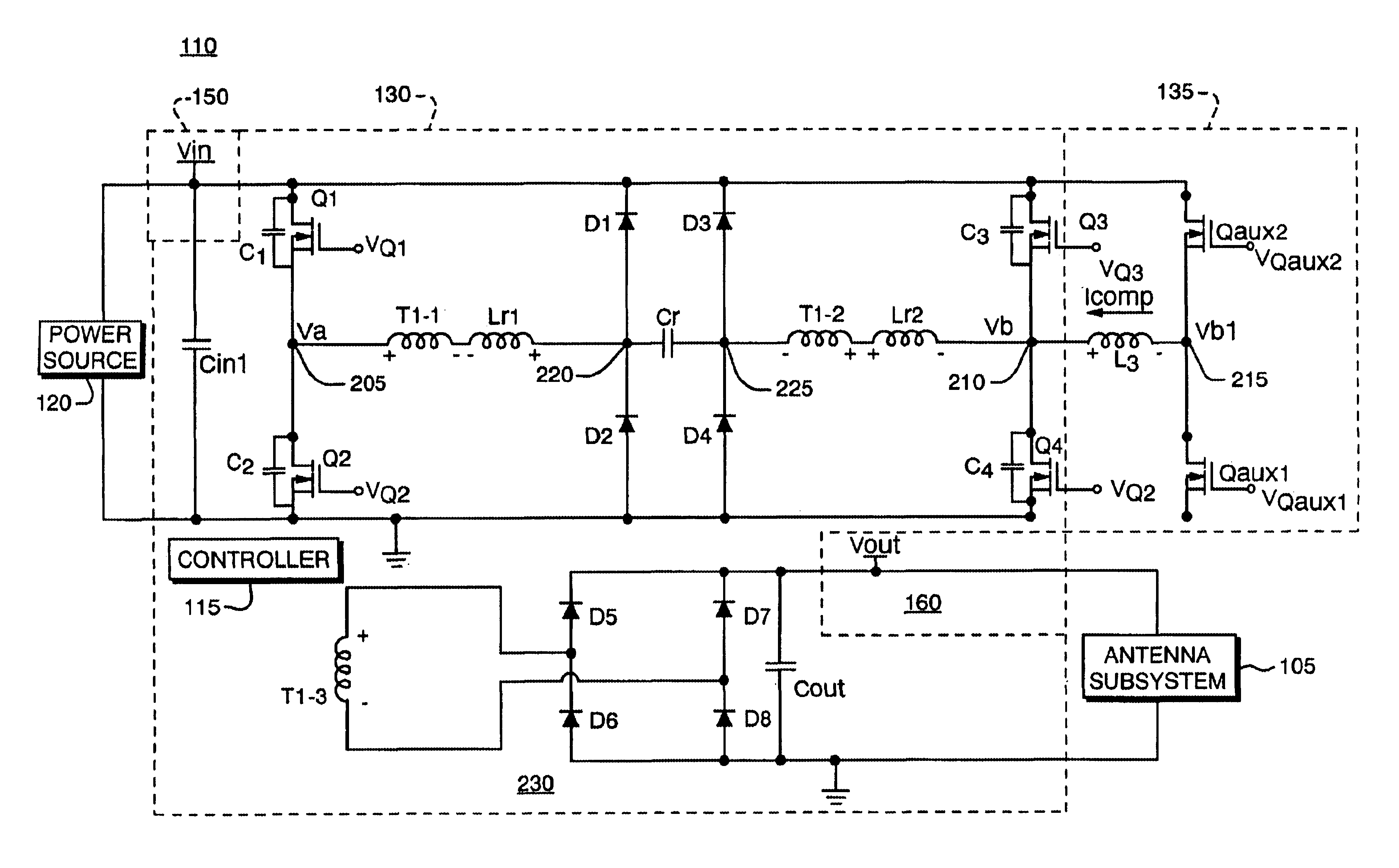
One aspect of the present invention involves providing zero-voltage switching in a power converter device even during relatively low output load conditions. To achieve this end, an electronic circuit such as a compensation circuit of a switching power supply device automatically generates a zero-voltage switching current that increases as an output load is reduced. As a result of extending zero-voltage switching to low load conditions, a power converter device provides a cleaner output voltage signal and maintains high efficiency over the full load range and therefore is well-suited for use in a wider variety of applications.
The auxiliary switches coupled to the inductor are optionally controlled by at least a portion of the time-varying control signals that are also used to control a set of main power switching transistors. Supporting common use of control signals for the different switching circuits reduces the complexity of a controller that would otherwise have to generate extra control signals to drive the auxiliary switches.

Problems solved by technology

Unfortunately, there are additional deficiencies associated with the aforementioned approaches to improving the operating characteristics of power supply devices and, more specifically, power converters.
For example, the use of conventional filters to reduce excessive noise on the output of a power converter can be cost or weight prohibitive, especially for megawatt power subsystem applications.
Thus, even though conventional filters may be effective, their use may be impractical.
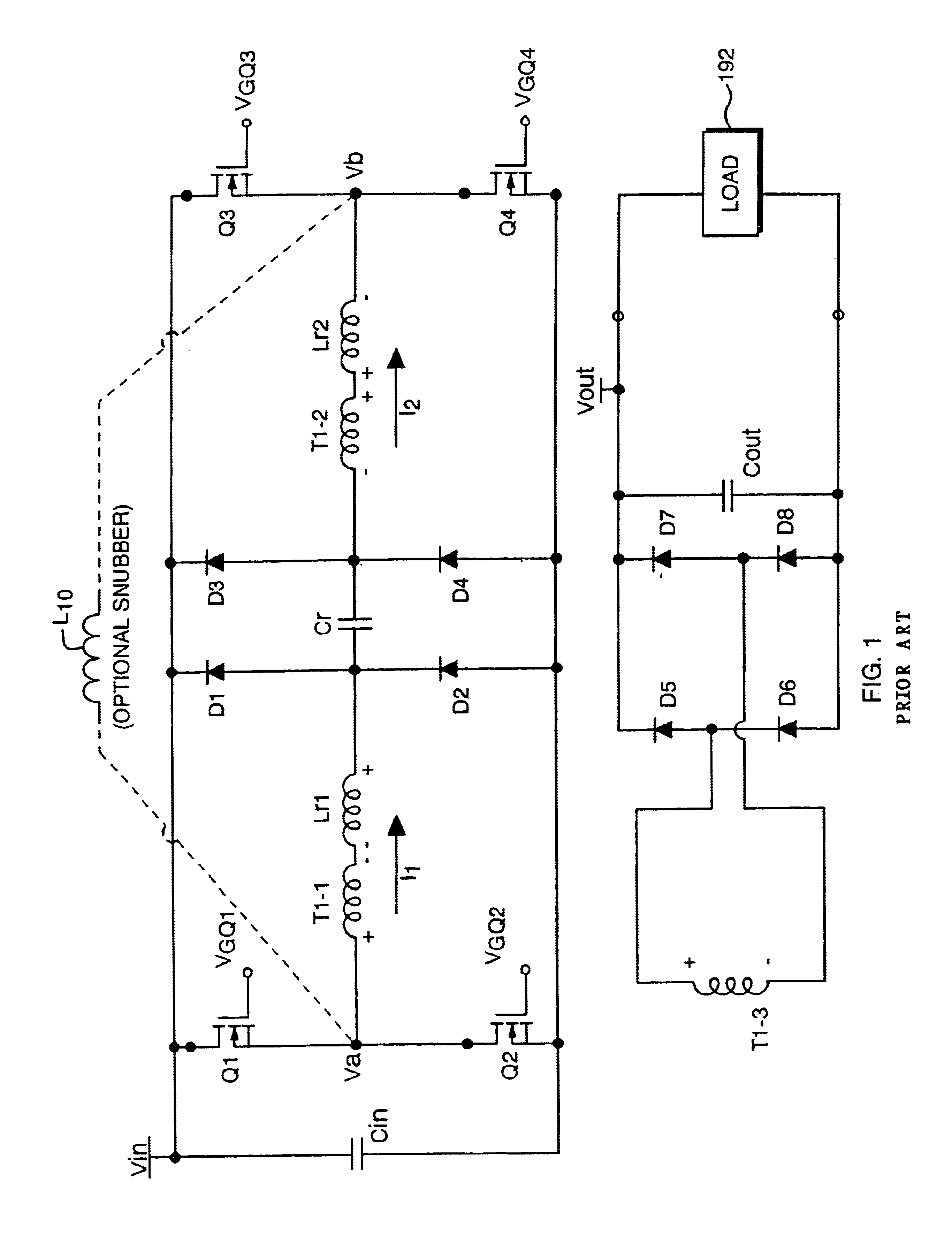
Use of a conventional snubber circuit to reduce noise or ripple on the output voltage of a power converter circuit also has drawbacks.
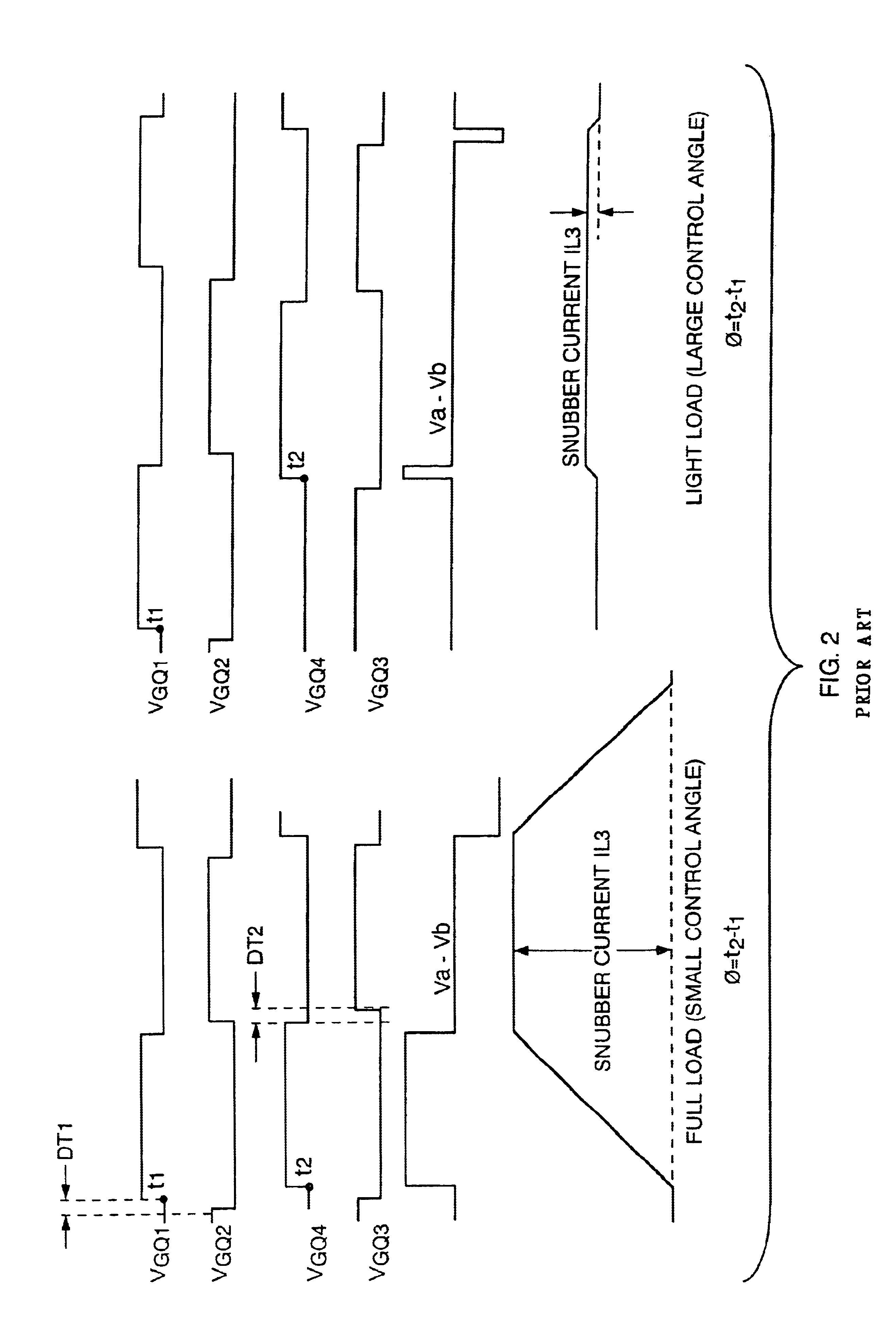
This reduction in snubber current typically results in unacceptable ripple and noise on the output of the power converter device at low load conditions.
Use of such a power converter device incorporating conventional snubber circuits is therefore limited because they can only be used to drive heavier loads.
Another undesirable artifact associated with conventional snubber circuits is reduced power conversion efficiency.

Method used


Image

  • Method and apparatus for converting power
  • Method and apparatus for converting power
  • Method and apparatus for converting power

Examples


Embodiment Construction

One aspect of the present invention is to adjust a compensation current such as a zero-voltage switching (ZVS) current in a power converter so that the converter produces a cleaner power signal and maintains high efficiency over the full load range. As previously discussed in the summary, a power converter increases a zero-voltage switching current in response to a reduced (or decreasing) load condition.

This technique of adjusting zero-voltage switching current is used so that sufficient zero-voltage switching current is produced at low load conditions, during which minimal power is delivered by the converter to power the load. A cleaner power signal (low noise, ripple, etc.) is produced at light loads due to increased zero-voltage switching. The generation of lower noise and output ripple voltage throughout a load range enables the power supply to operate with the burden of having to synchronize with the radar's PRF.

At heavier loads, the power converter reduces the zero-voltage swi...


PUM


Abstract

A power converter provides power to a phased-array radar antenna system. The converter adjusts its internal zero-voltage switching current so that it efficiently provides a clean power signal over a wide range of potential loads. More specifically, the zero-voltage switching current is increased in response to a decrease in load. The zero-voltage switching current in the converter can be maintained based on use of the same control signals that are otherwise used to regulate (via switching) the voltage output of the converter.

Description

BACKGROUND OF THE INVENTIONPower supplies that deliver power to phased array radar systems must comply with stringent standards. Otherwise, unwanted deviations such as spikes, noise and ripple on the output voltage of the power supply will cause radar system failures. The requirements for clean power are even more stringent for applications in which the phased array antenna system operates asynchronously with respect to the radar's PRF (Pulse Repetition Frequency).In order to comply with the stringent power supply requirements required by phased array radar systems, manufacturers can include extra circuitry in DC / DC power converter circuits so that they provide cleaner power signals.One technique to provide cleaner power signals involves the use of filters. For example, specifically designed and strategically placed filters sometimes can be used to eliminate unwanted deviations on the output voltage of a power supply.Another technique to provide cleaner power on the output of power ...

Claims


Application Information

Patent Timeline
IPC IPC(8): H01Q3/30H01Q3/26
CPCH01Q3/30H01Q3/26
Inventor JACOBSON, BORIS SOLOMON
Owner RAYTHEON CO
Learn More