
Stabilized tap mounting assembly

a technology of mounting assembly and stabilizer, which is applied in the field of remote sensing, can solve the problems of restricted innovation of this devi

Inactive Publication Date: 2005-03-29
CENTURY INDS
View PDF12 Cites 14 Cited by
  • Summary
  • Abstract
  • Description
  • Claims
  • Application Information

AI Technical Summary

Benefits of technology

"The invention is a device that allows conventional manifold / transmitter assemblies to be attached to orifice fittings. It provides a stable mount that ensures the attachment is secure. The device can be used with different types of orifice fittings and is easy to install. The technical effect of this invention is to provide a reliable and flexible attachment for measuring and controlling fluid flow in industrial applications."

Problems solved by technology

The novelty of this device is restricted to the stabilizing mount itself.

Method used


Image

  • Stabilized tap mounting assembly
  • Stabilized tap mounting assembly
  • Stabilized tap mounting assembly

Examples


Embodiment Construction

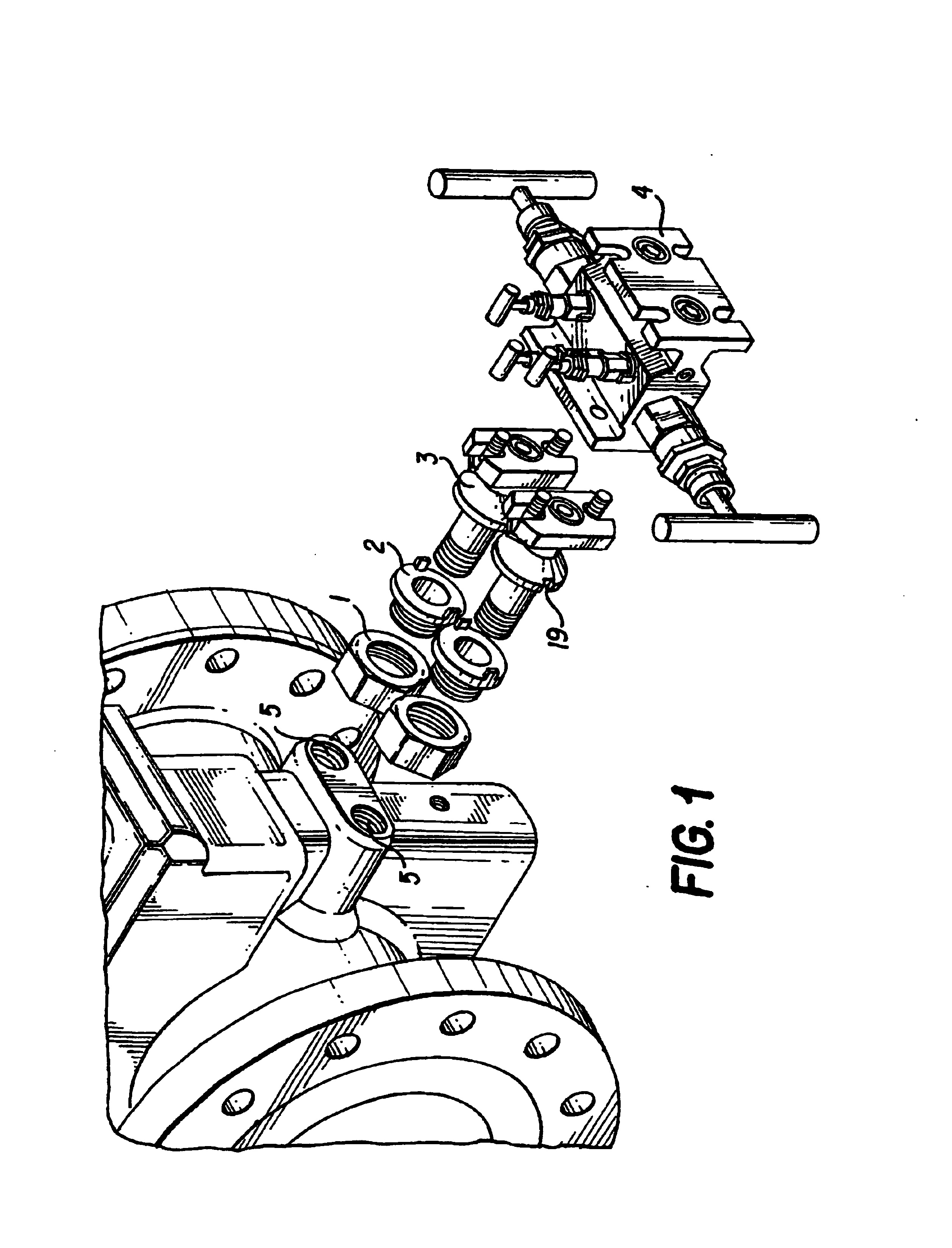
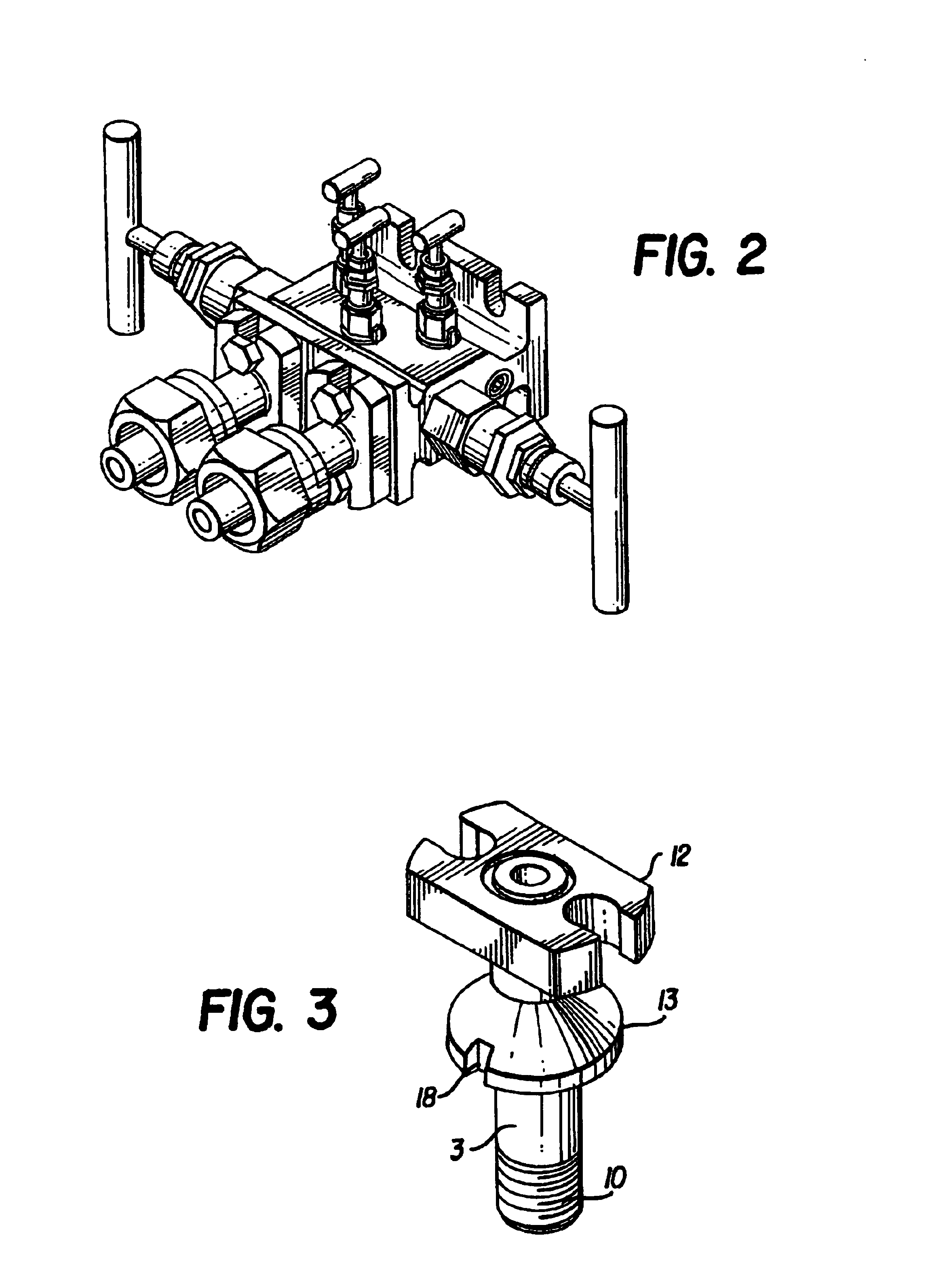
There are two tap assemblies required for each manifold (4) installation. Each tap assembly consists of three pieces. The tap (3), the stabilizing tube (2) and the stabilizing nut (1). The tap consists of a male NPT threaded end (1) and a flanged end (12). The flanged end (12) is for attachment to a conventional manifold (4). The tap (3) also includes a stabilizing flange (13) which is integral with the tap (3) and which his located between the NPT thread end (10) and the manifold connection flanged end (12).

The tap (3) is installed as follows. The stabilizing tube (2) and the stabilizing nut (1) are threaded together. The tap (3) is inserted through bore (14) in the stabilizing tube (2) and the stabilizing nut (1). The tap (3) is threaded into the orifice fitting (5). One end of the stabilizing tube (2) has a flat surface (15) with two projections (16)(17). These two projections (16)(17) fit into mating recesses (18)(19) on the stabilizing flange (12) located on the tap (3). The st...


PUM

PropertyMeasurementUnit
pressureaaaaaaaaaa
areaaaaaaaaaaa
volumeaaaaaaaaaa

Abstract

A method and apparatus are directed to reduce the load from the threads on taps on an orifice plate or orifice fitting. The apparatus includes a tap (3) having an NPT threaded end (1) and a flanged end (12) and an intermediate flange (13) which engages with a stabilizing tube (2) placed around the tap (3). In use, a stabilizing nut (1), previously threaded on the stabilizing tube (2), is unthreaded thereby forcing the stabilizing tube (2) against the intermediate flange (13) and transferring at least some of the weight off the threads (1) of the tap (3).

Description

BACKGROUND OF THE INVENTION1. Field of the InventionThis invention relates to the remote sensing of pressure drops across an orifice plate in a pipeline and particularly to a stabilize tap mounting assembly to facilitate, stabilize and reduce vibration of the transmitter and associated apparatus, such as valved manifold blocks connecting the transmitter to taps on an orifice plate or orifice fitting.2. Description of the Related ArtThe gas industry makes extensive use of orifice plates for volume measurements. Orifice plates are artificial constrictions in a pipeline. As a result of this constriction there is a pressure drop from the upstream side of the orifice plate to the downstream side of the orifice plate. There is a relationship between the pressure drop and the amount of gas flowing through the pipeline. The pressure drop can be measured which in turn allows a determination of the flow through the pipeline.The pressure drop is measured using electronic transmitters. These tr...

Claims


Application Information

Patent Timeline
Patent Type & Authority Patents(United States)
IPC IPC(8): F16L23/00G01L19/00
CPCG01L19/0007G01L19/0015Y10T29/53987Y10T137/612
Inventor HUTTON, PETER B.
Owner CENTURY INDS
Learn More