
Car wash controller

a technology for car wash and controller, applied in the direction of electric controllers, vehicle cleaning, instruments, etc., can solve the problems of increasing the cost and complexity of the car wash system, and achieve the effect of eliminating wiring within the car wash environmen

Inactive Publication Date: 2005-03-22
DELAWARE CAPITAL FORMATION
View PDF4 Cites 8 Cited by
  • Summary
  • Abstract
  • Description
  • Claims
  • Application Information

AI Technical Summary

Benefits of technology

The present invention is a controller for operating the various electrical devices, valves and motors in a car wash that eliminates high voltage / current wiring from a central controller to the various components in the car wash environment. The present invention utilizes a central controller that is connected to a plurality of input boards and output relay boards through communication cables, such as telephone wires, such that the central controller can control the operation of the electrical devices through the telephone wires.
The central controller is positioned in a central location within the car wash environment. An input board is positioned near each of the electrical input devices used in the car wash. For example, an input board is positioned near a program selector and a separate input board is positioned near input devices such as sensors or speed indicators. Each of the input boards includes a plurality of cable connectors that allow the input board to be coupled to the central controller through the telephone cable. Additionally, the cable connectors allow the input boards to be connected to each other such that data from one of the input boards can be transferred to the other input board and ultimately received by the central controller. The ability to join the multiple input boards reduce the amount of wiring within the car wash environment.
The central controller is coupled to a plurality of output relay boards through communication cables, such as standard telephone wire. Each of the output relay boards includes a plurality of cable connectors, a plurality of relays and a plurality of switches. The multiple cable connectors allow the relay boards to be “daisy chained” together. Connecting the relay boards together allows for the reduction of cabling from the central controller to each of the individual output relay boards. Particularly if multiple output devices are operated based upon the same command signal from the central controller, the “daisy chained” relay boards allow multiple output devices to be operated upon generation of a single output command from the central controller.
In accordance with the present invention, the input boards and the output relay boards are located remotely from the central controller and communicate with the central controller only through a communication cable. The communication cable does not carry the electrical power to operate the output electrical devices or the input electrical devices, as was the case in the prior art. By eliminating the electrical conduits between the central controller and the various devices, the system of the invention can be set up without the use of a trained electrician. Further, the daisy chaining of the input boards and the output relay boards eliminates wiring within the car wash environment.

Problems solved by technology

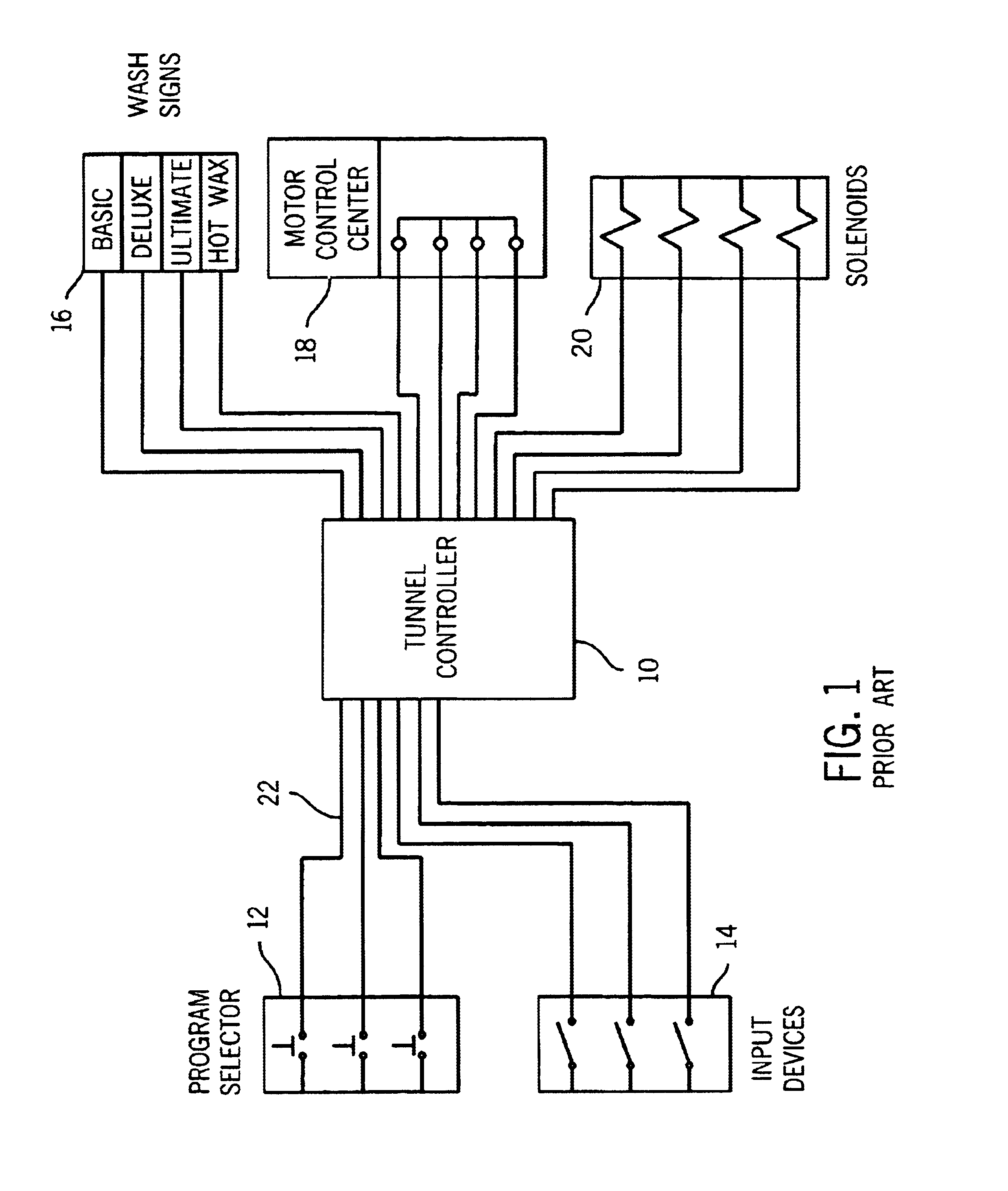
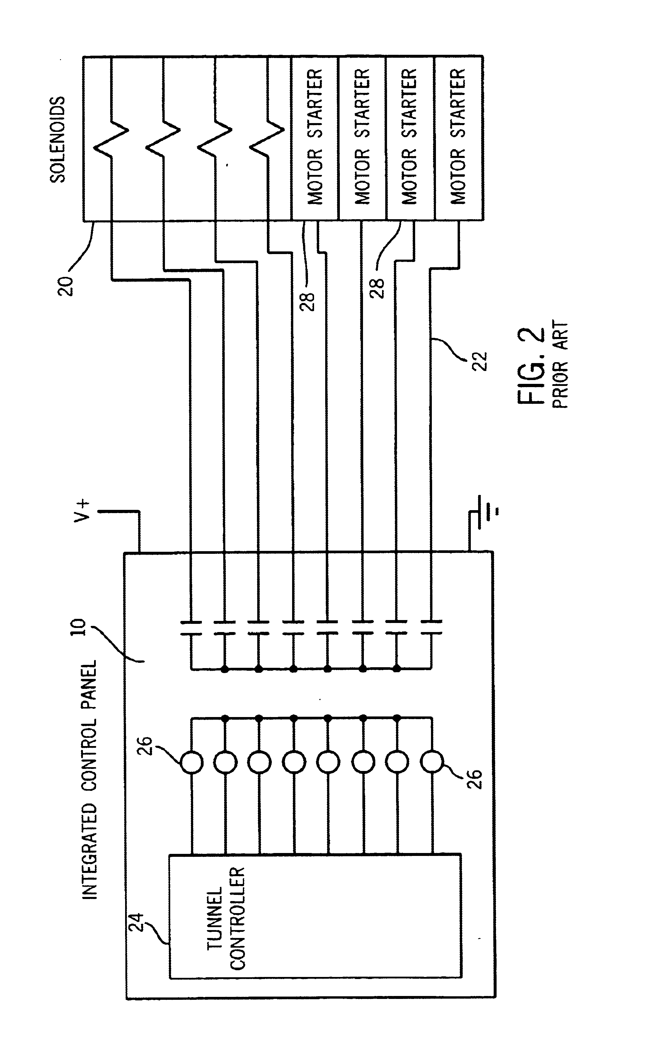
Since the solenoids and motor starters are positioned at different locations within the tunnel car wash, the initial set up of the car wash requires an electrician to run long lengths of shielded electrical conduit, which increases the cost and complexity of the car wash system.

Method used


Image

  • Car wash controller
  • Car wash controller
  • Car wash controller

Examples


Embodiment Construction

Referring first to FIG. 3, thereshown is the central car wash controller 30 of the present invention. The central tunnel wash controller 30 includes a central process computer 32 that controls the operation of the entire car wash. In the preferred embodiment of the invention, the process computer 32 is utilized in connection with a tunnel car wash, although other types of car wash environments are contemplated as being within the scope of the present invention.

As can be seen in FIG. 3, the process computer 32 is connected to a plurality of input boards 34 and a plurality of output relay boards 36 using a communication cable, such as a standard telephone cable 38. Each of the telephone cables 38 include a conventional RJ-11 connector on each of its ends. As illustrated in FIG. 3, the input boards 34 are installed next to both a program selector input device 40, such as a button box that allows a customer to select service options, and a bank of input devices 42 that feed sensor infor...


PUM


Abstract

A car wash controller for receiving input data from a plurality of remote input devices and for controlling the operation of multiple remote output electrical devices. The central controller is coupled to a series of input boards by a communication cable, such as a telephone cable, to receive input data from the input electrical devices. The input boards can be coupled to each other to reduce the amount of wiring within the car wash environment. The central controller is further connected to a series of output relay boards, each of which are connected to a supply of power. The central controller is connected to the output relay boards by a communication cable such that an output command can be sent to each relay board to supply electrical power to the output electrical devices. The relay boards can be coupled to each other to reduce the amount of wiring within the car wash environment.

Description

BACKGROUND OF THE INVENTIONThe present invention relates to a controller for operating various electrical devices, valves, motors and signs in a car wash environment. More specifically, the present invention relates to a controller for operating a tunnel car wash in which a central controller communicates with a plurality of relay boards, each of which are connected to a supply of power and are positioned to control the operation of one or more devices in the car wash.In previous car wash environments, such as shown in FIGS. 1 and 2, the car wash included a central controller that resides in a central control panel 10. The control panel 10 is connected to various car wash operating components, such as a series of program selector buttons 12 and input sensors or devices 14, a wash sign 16, a motor control center 18 and a bank or series of solenoids 20. The connections between the central control panel 10 and each of these devices is completed by a shielded electrical conduit 22. The ...

Claims


Application Information

Patent Timeline
Patent Type & Authority Patents(United States)
IPC IPC(8): B60S3/04B60S3/00G08C19/00
CPCB60S3/04
Inventor VAN KESSEL, JAN
Owner DELAWARE CAPITAL FORMATION
Learn More