
Serial data transmission system using minimal interface

a data transmission system and interface technology, applied in the direction of data switching networks, electrial characteristics varying frequency control, speed/phase control of synchronisation signal, etc., can solve the problem that the use of high frequency clocks in the interface generates undesirable radio frequency (rf) emissions, circuit designers have created expensive system serial transmission systems, and the system may require additional circuitry

Inactive Publication Date: 2005-03-22
INMUSIC BRANDS +2
View PDF10 Cites 4 Cited by
  • Summary
  • Abstract
  • Description
  • Claims
  • Application Information

AI Technical Summary

Benefits of technology

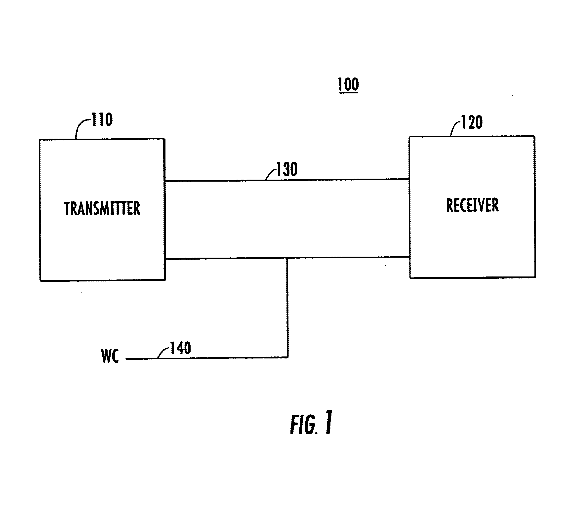
The present invention provides for a simple interface of a data line and one clock line between a transmitter and receiver.

Problems solved by technology

The use of high frequency clocks in an interface generates undesirable radio frequency (RF) emissions.
Circuit designers have created expensive system serial transmission systems in order to attempt to compensate for the large interface requirements and to comply with emission standards.
If such a clock is not readily available to the designer, the system may require additional circuitry.
Conventional transmitters and receivers are not integrated onto a single chip due to the size of the phase locked loop (PLL) typically included in the devices.
Using more than one chip for the transmitter or receiver increases the cost and size of the system.

Method used


Image

  • Serial data transmission system using minimal interface
  • Serial data transmission system using minimal interface
  • Serial data transmission system using minimal interface

Examples


Embodiment Construction

Reference will now be made in detail to embodiments consistent with this invention that are illustrated in the accompanying drawings. The same reference numbers in different drawings generally refer to the same or like parts.

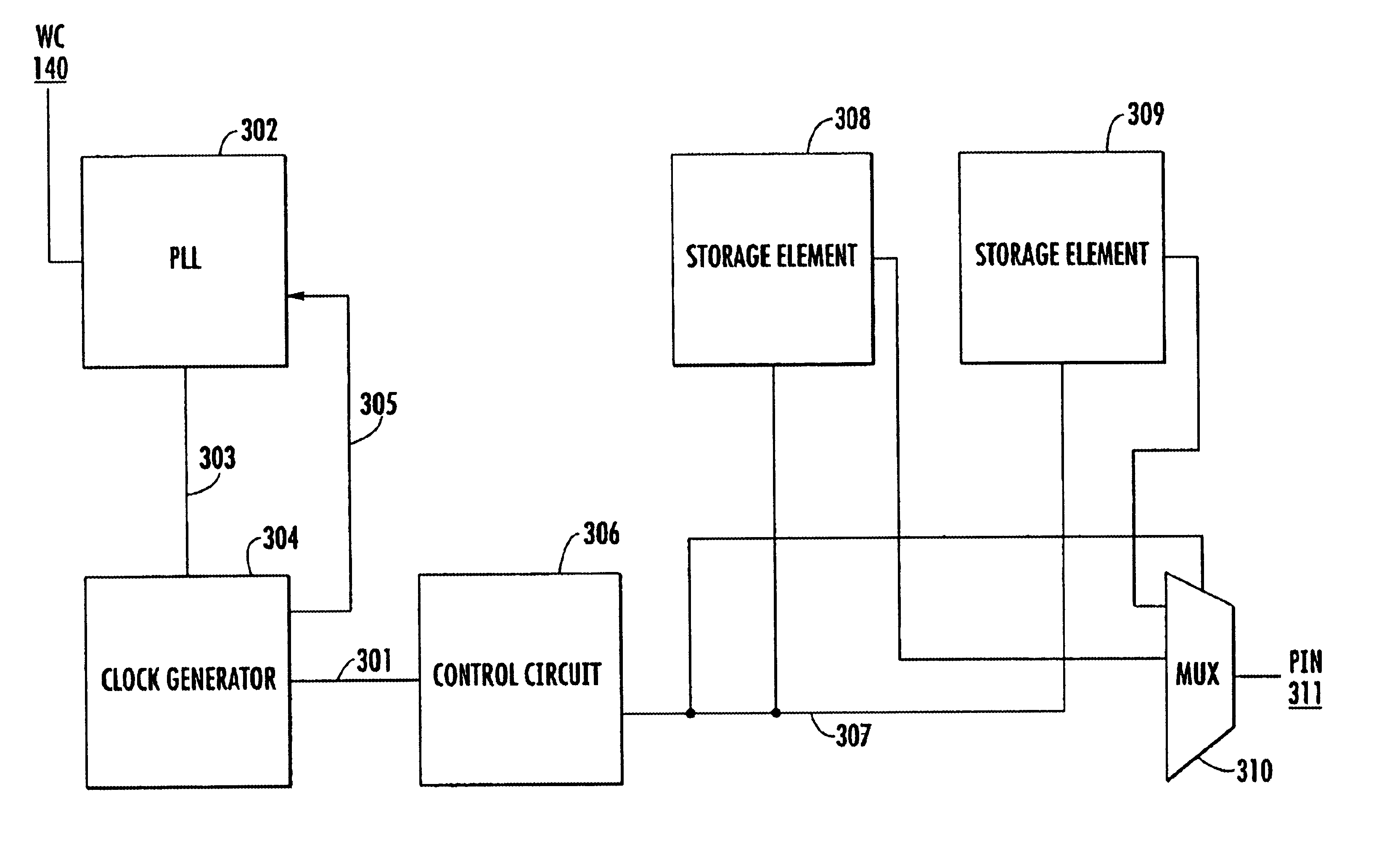
The present invention provides for a transmitter and receiver that receive a single word clock. Additional clocks are then generated locally to be used in a control circuit to generate control signals. The control signals control the reception and transmission of data. System interface is simplified because only a single external clock is required. Excessive emissions are reduced when the external clock is not a high frequency clock. Any high frequency clocks needed are generated locally.

The present invention further provides for a transmitter that may be integrated onto a single chip and a receiver that may be integrated onto a single chip. A loop filter in a phase locked loop in the transmitter and receiver has a charge pump and capacitor that are small enough...


PUM


Abstract

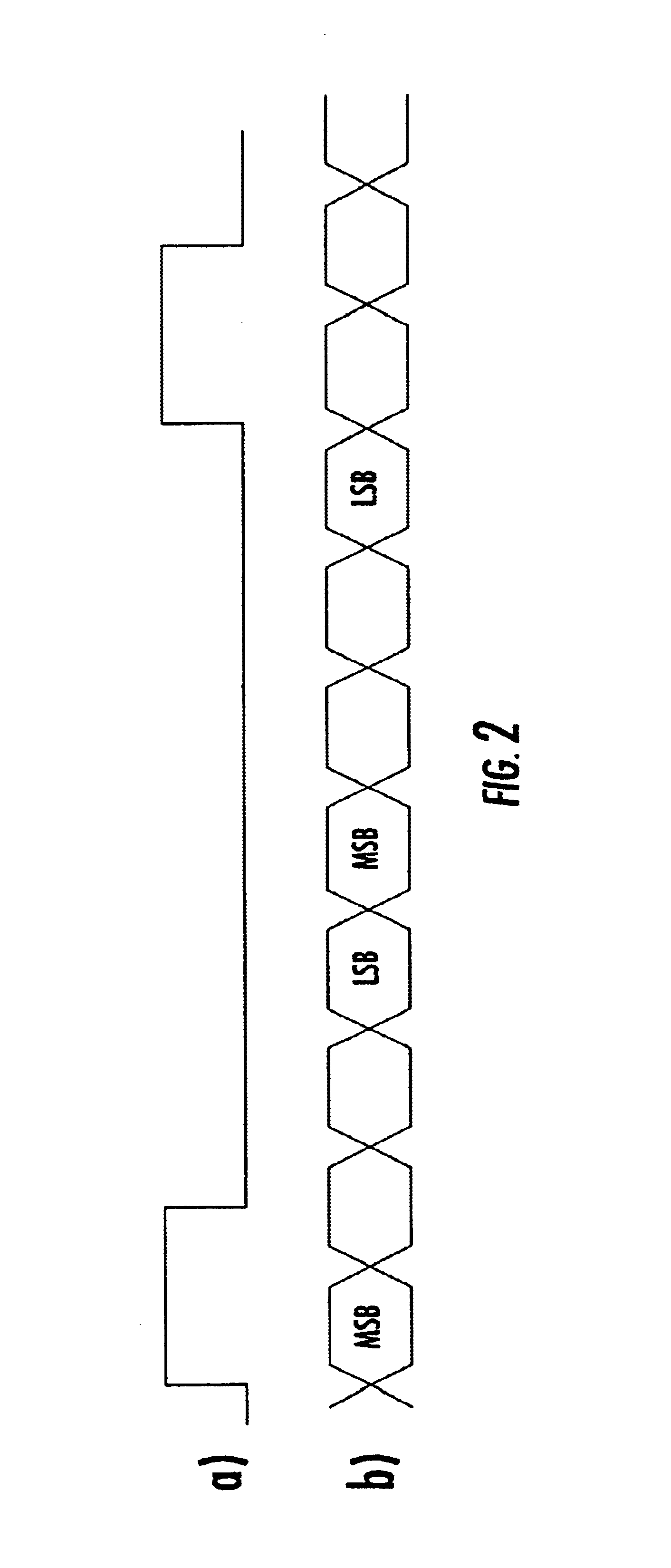
A data transmission system comprising a transmitter and a receiver that use a single external word clock to generate all needed clocks locally using a clock generator and a phase locked loop. Data words are transmitted on a transmission line based on a single transition of the word clock. The transmitter and receiver may each be incorporated on a single chip.

Description

I. BACKGROUND OF THE INVENTIONThe present invention relates generally to data transmission systems, and more particularly to serial data transmission systems for transmitting data words in a sequence of data bits.Data transmission systems require a clock to coordinate transmission of data.Traditional serial transmission systems require a data line and three clocks—a word clock, a high frequency bit clock, and a high frequency system clock. Example values for these lines are as follows: word clock at 48 Khz, bit clock at 3.072 MHz, a system clock at 12.288 MHz and a data line that sends data at the 3.072 MHz rate. An example system that uses multiple clock signals is the system described in U.S. Pat. No. 4,755,817 to Vandenbulke et al. that uses two high-frequency clock signals to transmit data words.The use of a plurality of clocks increases the size of an interface between a transmitter and receiver. The use of high frequency clocks in an interface generates undesirable radio frequ...

Claims


Application Information

Patent Timeline
IPC IPC(8): H03L7/089H03L7/099H03L7/107H03L7/08H04L7/02
CPCH03L7/0893H03L7/0995H04L7/02H03L7/1072H03L7/107
Inventor BARR, KEITHTHOMSON, FRANKCELI, PETER
Owner INMUSIC BRANDS
Learn More