
Double-acting hydraulic pressure intensifier

a technology of hydraulic pressure intensifier and double-acting, which is applied in the direction of non-mechanical valves, valve details, mechanical apparatuses, etc., can solve the problems of inability to change the valve element to the other position, defective switching of the valve element, etc., and achieve the effect of increasing reliability

Inactive Publication Date: 2005-03-15
MINIBOOSTER HYDRAULICS
View PDF6 Cites 21 Cited by
  • Summary
  • Abstract
  • Description
  • Claims
  • Application Information

AI Technical Summary

Benefits of technology

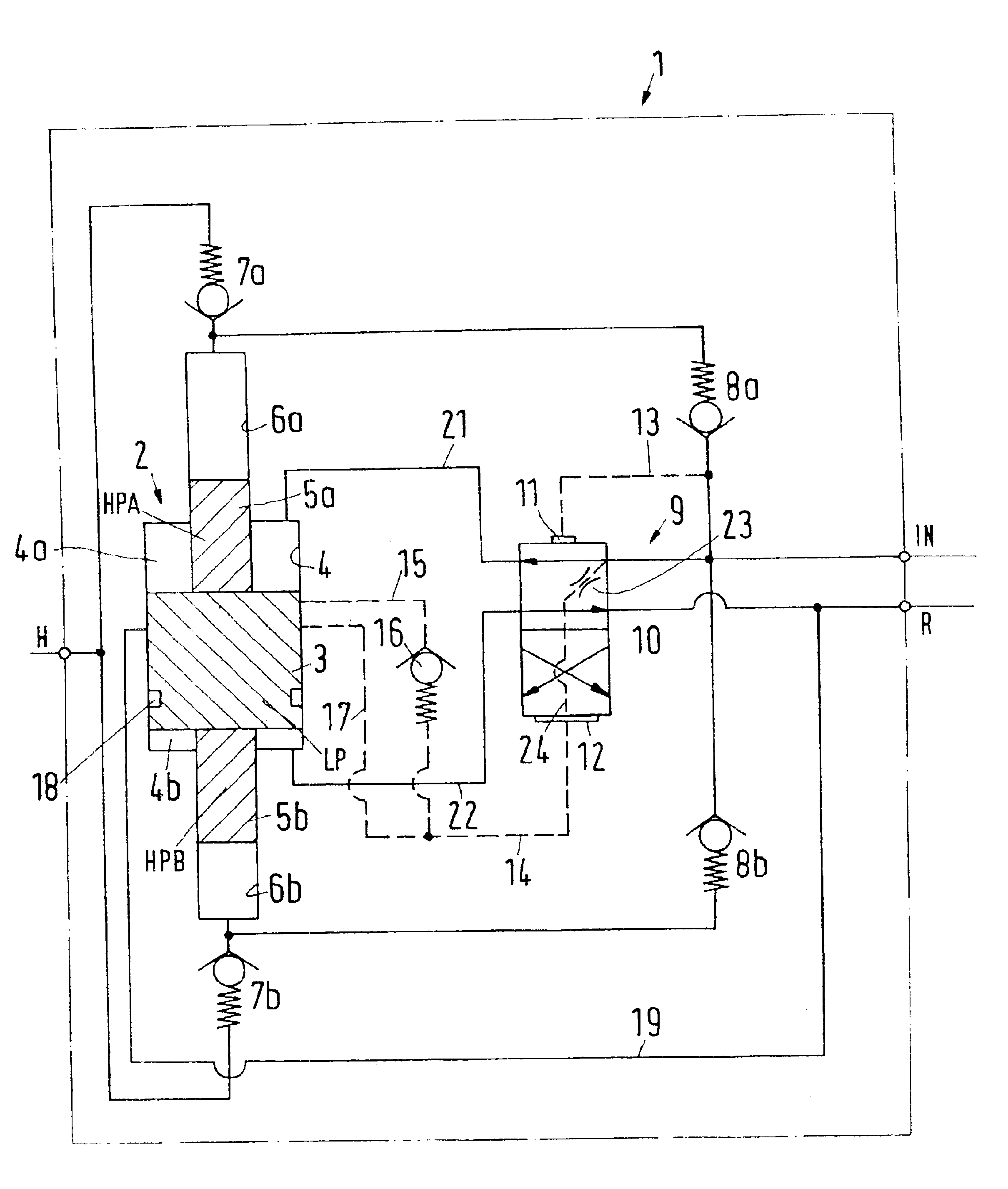
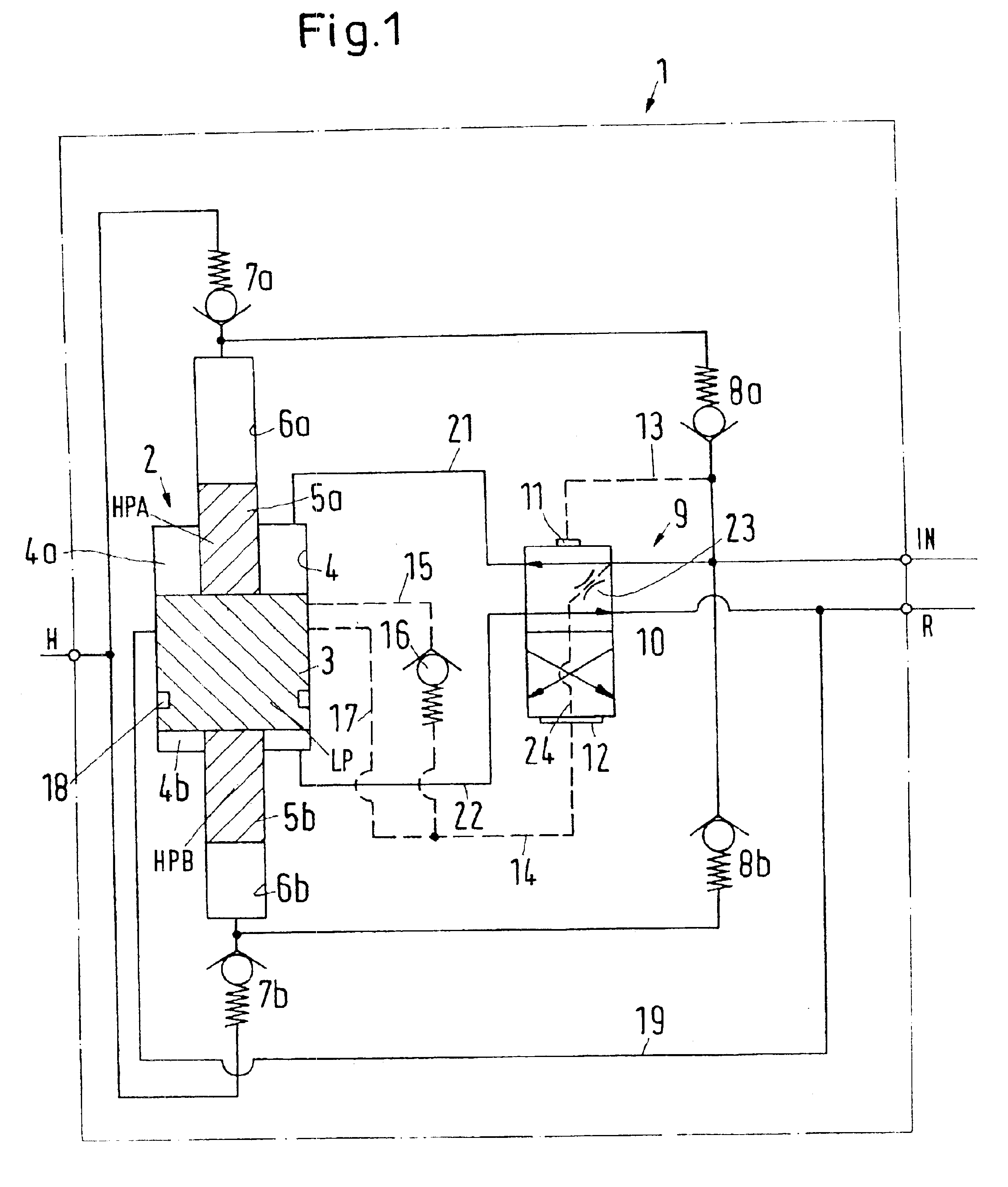
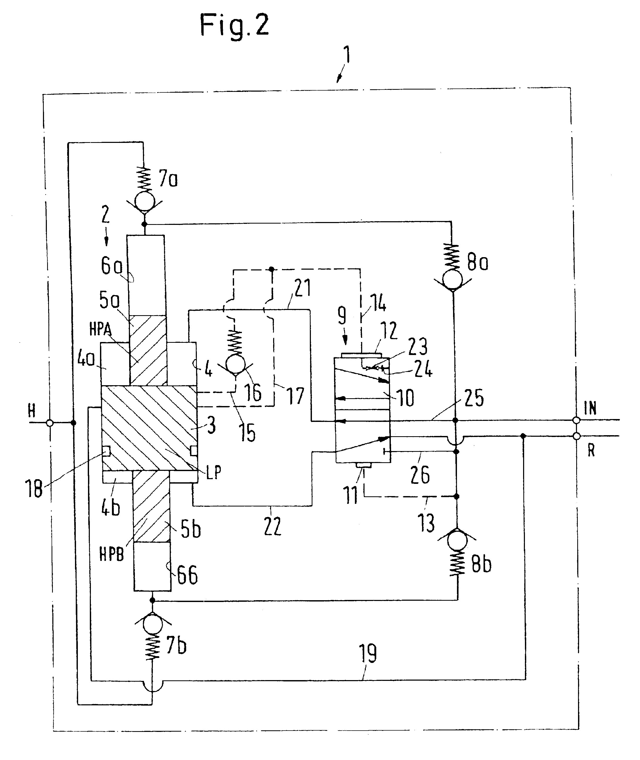
It is the primary object of the present invention to increase the reliability.
Preferably, each shuttle valve comprises its own control pressure chambers, wherein at least the second control pressure chambers are separated from each other. This is a relatively simple option for making the pressurization of the two valve elements different.

Problems solved by technology

Erroneous or defective switching of the valve element to the other position on account of a leak cannot take place because the pressure from a higher plane, namely the supply connection, is maintained.

Method used


Image

  • Double-acting hydraulic pressure intensifier
  • Double-acting hydraulic pressure intensifier
  • Double-acting hydraulic pressure intensifier

Examples


third embodiment

FIG. 3 shows a third embodiment in which identical and corresponding parts are given the same reference numbers.

The construction of the second pilot line 14 has changed. In the branch 15 a non-return valve 16 is now no longer provided. In return, an additional line 20 is provided between the supply connection IN and the low-pressure cylinder 4. The line 20 opens out into the low-pressure cylinder 4 in such a way that the groove 18 on the low-pressure piston 3 in an end position of the low-pressure piston 3 can make a connection between the line 20 and the branch 15 of the second pilot line 14. As soon as this connection is made, the valve element 10 is displaced into its position not shown in FIG. 3, this being under the action of the pressure in the second control pressure chamber 12 which acts on a larger pressure application area than in the first control pressure chamber 11 and corresponds to the pressure at the supply connection IN. The pressure in the second control pressure c...


PUM


Abstract

A double-acting hydraulic pressure intensifier includes a supply connection, a return connection, a high-pressure connection. An intensifier piston assembly includes a low-pressure piston arranged in a low-pressure cylinder and two high-pressure pistons connected to the low-pressure piston each arranged in a high-pressure cylinder. A switching valve assembly includes a displace able, hydraulically controlled valve element which on its two opposite sides in the direction of displacement has control pressure chambers with pressure application areas of different sizes, namely, a first control pressure chamber with a smaller pressure application area and a second control pressure chamber with a larger pressure application area. A stop plug is arranged between the second control pressure chamber and the supply connection.

Description

BACKGROUND OF THE INVENTION1. Field of the InventionThe present invention relates to a double-acting hydraulic pressure intensifier with a supply connection, a return connection, a high-pressure connection, an intensifier piston assembly comprising a low-pressure piston in a low-pressure cylinder and two high-pressure pistons connected to the low-pressure piston each in a high-pressure cylinder, and with a switching valve assembly comprising a displaceable, hydraulically controlled valve element which on its two opposite sides in the direction of displacement comprises control pressure chambers with pressure application areas of different size, namely a first control pressure chamber with a smaller pressure application area and a second control pressure chamber with a larger pressure application area.2. Description of the Related ArtA double-acting hydraulic pressure intensifier of this kind is known from U.S. Pat. No. 4,659,294. The switching valve comprises a valve slide which can...

Claims


Application Information

Patent Timeline
Patent Type & Authority Patents(United States)
IPC IPC(8): F04B9/113F04B9/00
CPCF04B9/113
Inventor HANSEN, LEIFCLAUSEN, PETER J. M.ESPERSON, CHRISTENPETERSEN, JAN
Owner MINIBOOSTER HYDRAULICS
Learn More