Eureka AIR delivers breakthrough ideas for toughest innovation challenges, trusted by R&D personnel around the world.

Bicycle rear suspension

a rear suspension and bicycle technology, applied in the field of rear wheel suspension assembly, can solve the problems of wasting effort, the rear suspension system commonly incorporated in engine-driven vehicles, such as motorcycles, has proved ineffective for pedal-driven vehicles, and the rear shock absorber has a higher sensitivity of the inertia valv

Inactive Publication Date: 2005-03-15
SPECIALIZED BICYCLE COMPONENTS INC
View PDF54 Cites 38 Cited by
  • Summary
  • Abstract
  • Description
  • Claims
  • Application Information

AI Technical Summary

Benefits of technology

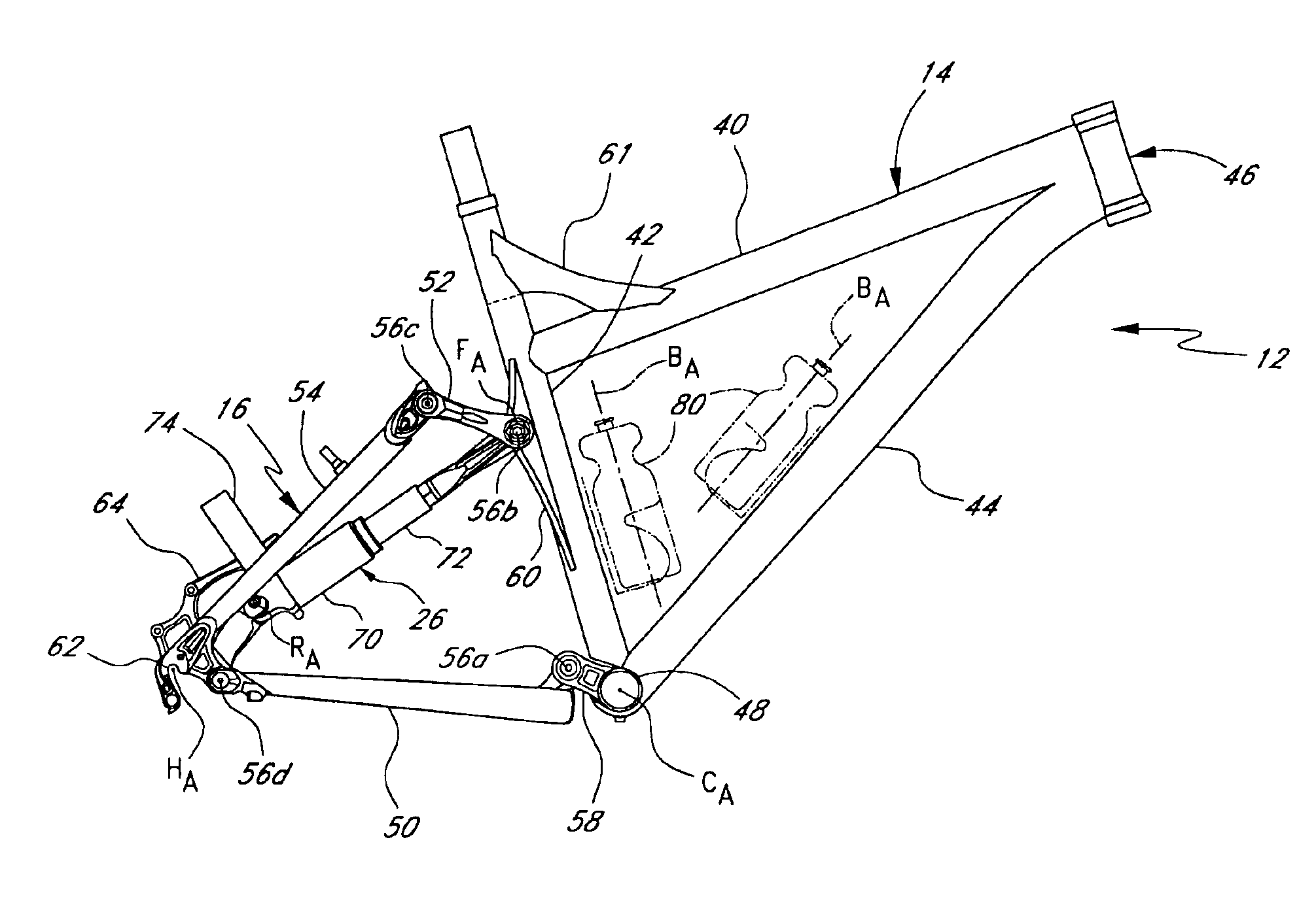
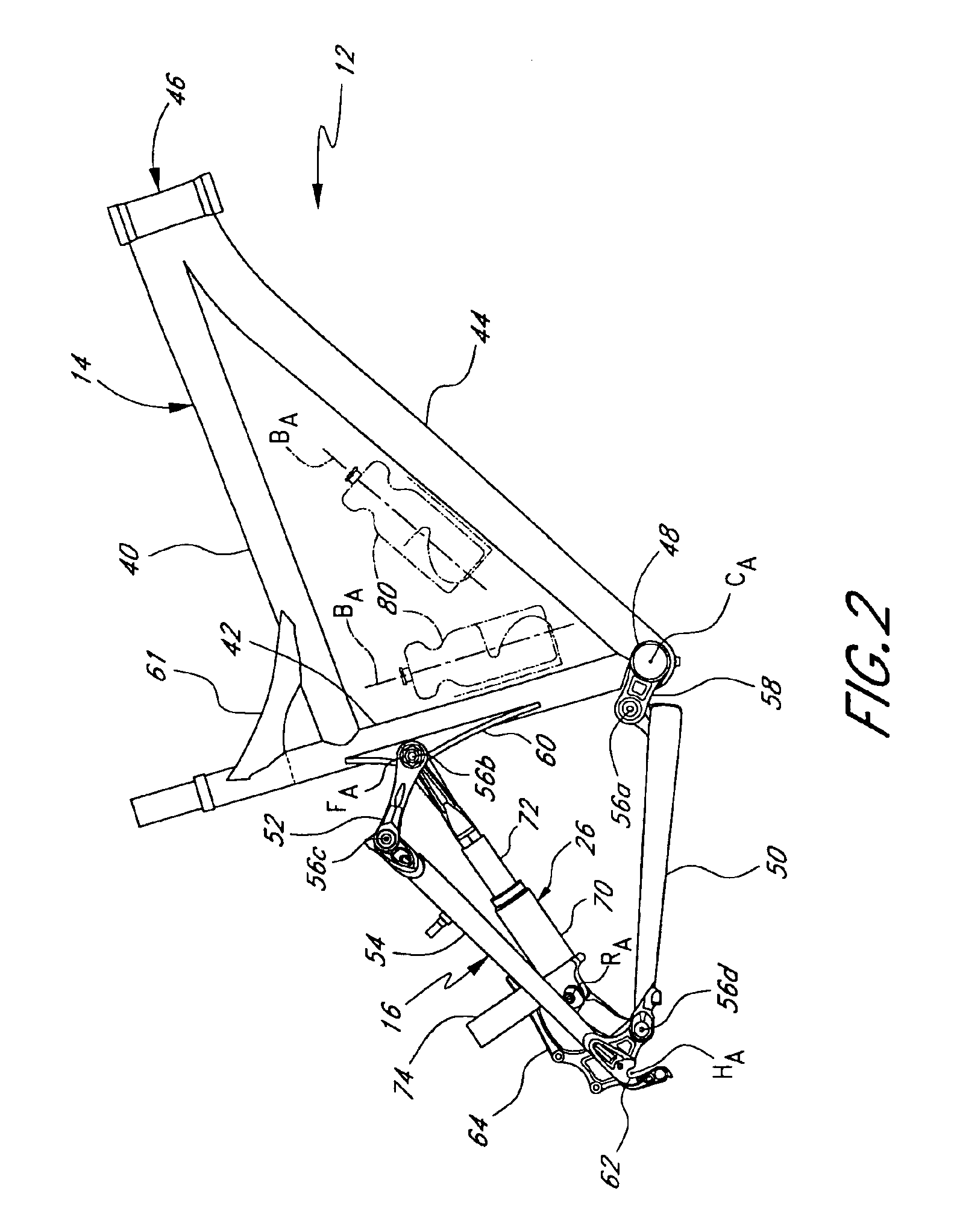
Preferred embodiments of the present invention desirably inhibit pedal-induced forces and brake-induced forces from acting on the rear suspension while maintaining the use of a traditional triangular mainframe of the mountain bike. In addition, one end of the rear shock absorber is desirably positioned close to the axis of rotation of the rear wheel, or the hub axis. Accordingly, if an inertia valve is incorporated within the rear shock absorber, it may be positioned near the hub axis, where the greatest inertial forces are present. As a result, the sensitivity of the inertia valve is increased.

Problems solved by technology

However, because mountain bikes are typically pedal-driven, i.e., use the rider's power output to propel the bicycle, the provision of rear suspension, especially, may undesirably absorb a rider's power output, resulting in wasted effort.
Accordingly, rear suspension systems commonly incorporated on engine-driven vehicles, such as motorcycles, have proven ineffective for use with pedal-driven vehicles, such as mountain bikes.
Rear suspension systems of engine-driven vehicles commonly emphasize strength over weight and, therefore, have not been widely incorporated on mountain bikes.
However, one problem associated with prior mountain bike rear suspension designs involves placement of the rear shock absorber.
Due to the relatively complex nature of common mountain bike rear suspension assemblies, the placement of the rear shock absorber has often precluded the use of a traditional triangular mainframe of the mountain bike.
As the down tube and the seat tube members of the mainframe have traditionally been provided with mounts, or bosses, for mounting of water bottle cages, many designs incorporating rear suspension assemblies have inhibited the use of one, or both, of the traditional water bottle cage locations due to the placement of the rear shock absorber.

Method used


Image

  • Bicycle rear suspension
  • Bicycle rear suspension
  • Bicycle rear suspension

Examples


Embodiment Construction

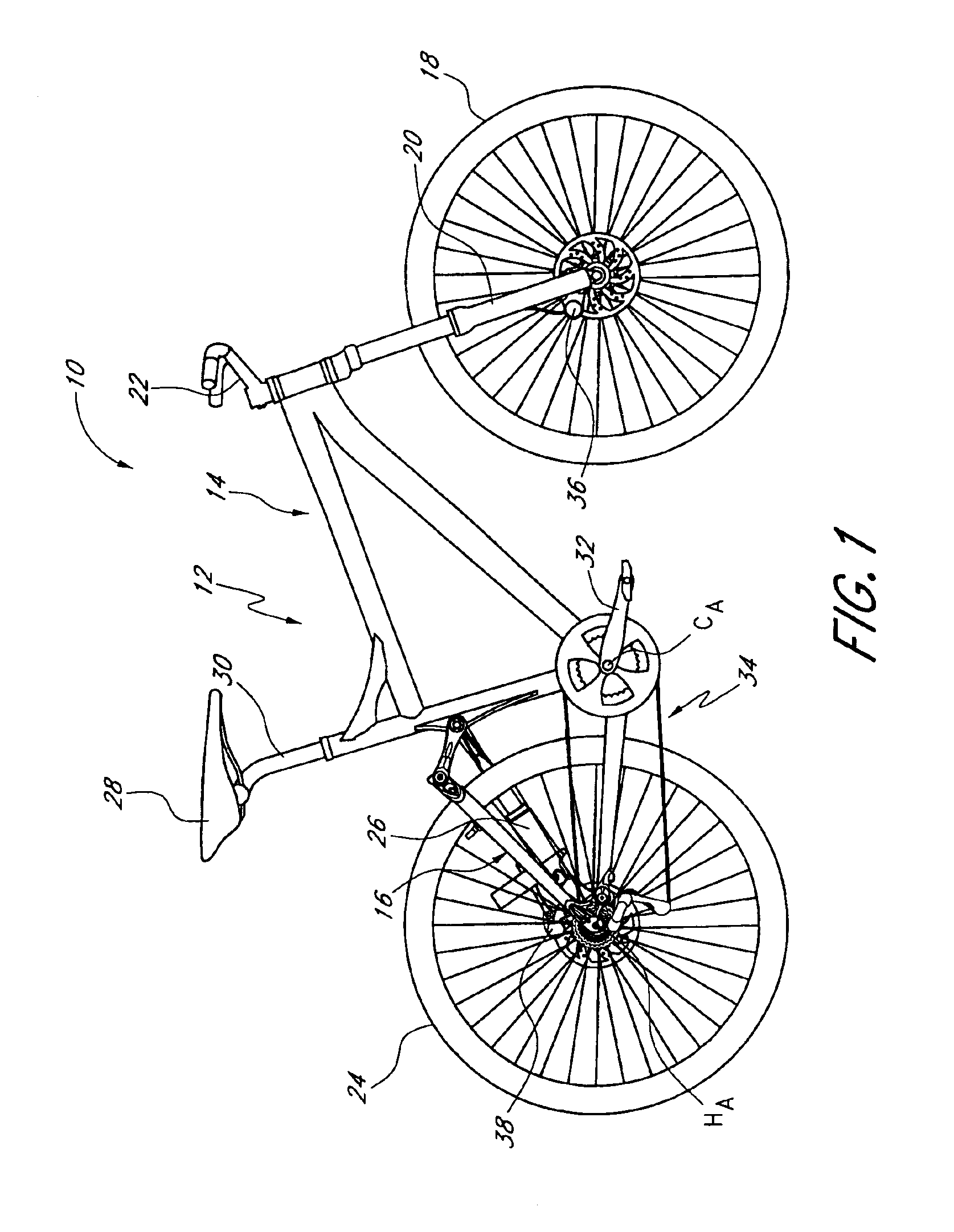
FIG. 1 illustrates an off-road bicycle, or mountain bike 10, including a preferred rear suspension assembly. The bicycle 10 is described herein with reference to a coordinate system wherein a longitudinal axis extends from a forward end to a rearward end of the bicycle 10. A vertical, central plane CP generally bisects the bicycle 10 and contains the longitudinal axis. A lateral axis extends normal to the longitudinal axis and within a horizontal plane. In addition, relative heights are generally expressed as elevations in reference to a horizontal surface on which the bicycle 10 is supported in an upright position. Similarly, relative forward and rearward positions are expressed as distances in reference to a vertical axis, which is normal to the horizontal surface. The above-described coordinate system is provided for the convenience of describing the embodiment illustrated in FIGS. 1-5, and is not intended to limit the scope of the present invention.

The bicycle 10 includes a fram...


PUM


Abstract

A bicycle including a frame having a main frame portion and an articulating frame portion pivotally mounted to the main frame portion and carrying a rear wheel of the bicycle at a hub axis. A shock absorber is operably connected between the main frame portion and the articulating frame portion to provide resistance to articulating motion of the articulating frame portion. A rearward end of the shock absorber preferably is pivotally mounted to the articulating frame portion at a location near the hub axis. The shock absorber preferably is positioned within a perimeter defined in a vertical plane generally by the articulating frame portion.

Description

INCORPORATION BY REFERENCEThe entireties of U.S. patent application Ser. No. 10 / 135,052, filed Apr. 29, 2002, and U.S. Provisional Patent Application No. 60 / 372,982, filed Apr. 15, 2002, are hereby expressly incorporated by reference herein and made a part of this specification.BACKGROUND OF THE INVENTION1. Field of the InventionThe present invention relates generally to vehicle suspension systems. More particularly, the present invention relates to a rear wheel suspension assembly suitable for use in connection with off-road bicycles.2. Description of the Related ArtOff-road bicycles, or mountain bikes, may be equipped with front and rear suspension assemblies operably positioned between the front and rear wheels, respectively, and the frame of the bicycle. Providing front and rear suspension on a mountain bike potentially improves handling and performance by absorbing bumps, and other rough trail conditions, which may be encountered while riding off-road. However, because mountain...

Claims


Application Information

Patent Timeline
Patent Type & Authority Patents(United States)
IPC IPC(8): B62K25/28B62K25/04
CPCB62K25/286B62K3/04
Inventor CHAMBERLAIN, JASON L.D'ALUISIO, CHRISTOPHER P.
Owner SPECIALIZED BICYCLE COMPONENTS INC
Why Eureka
Eureka Blog
Learn More