Recording-medium operating device, clock signal generating device and method for generating clock signal

a clock signal and operating device technology, applied in the direction of generating/distributing signals, digital signal error detection/correction, instruments, etc., can solve the problems of frequency difference or phase difference between a reference clock and data in a data region, frequency difference or phase difference between a reference clock and data, etc., to achieve low power consumption, suppress noise, and high correction accuracy

Inactive Publication Date: 2005-03-08
FUJITSU LTD
View PDF5 Cites 5 Cited by
  • Summary
  • Abstract
  • Description
  • Claims
  • Application Information

AI Technical Summary

Benefits of technology

[0014]The present invention has been made to solve the above-mentioned problems of the prior art. It is an object of the present invention to provide a recording-medium operating device, a clock signal generating device for the recoding-medium operating device, and a method for generating a clock signal for the recoding-medium operating device that satisfy both operation with a wide-range data transfer rate using delay line provided with not so large number of stages and high correction accuracy and are advantageous in terms of low power consumption and suppression of noises.

Problems solved by technology

Therefore, there is possibility that frequency difference and phase difference between a reference clock and data on a data region occur.
Furthermore, individual differences of devices and disks themselves can possibly cause frequency difference or phase difference between a reference clock and data on a data region.
However, the above-mentioned prior art has following problems.
That is, number of stages required for a delay line is too large.
However, this sacrifices highly accurate phase synchronization in case of high data transfer rate.
However, concerning a case of high data transfer rate, total delay quantity actually required can be achieved with a small number of stages in the delay line.
This means the delay line has a large number of unnecessary circuits.
As a result, power consumption is more than necessary.
Furthermore, if the number of stages in a delay line is excessively large, the fact itself is problematic.
This causes large noises and as secondary phenomena, erroneous operation to circuits around the delay lines, and characteristic deterioration take place.
Furthermore, delay quantities of respective buffer logics that constitute a delay line are not always uniform.
As the number of stages is larger, delay quantity variation among buffer logics affects operation of the delay line more seriously.
Therefore, accurate phase correction cannot be made and frequency of corrections to approximate a desired phase increases.
That is, it takes long for phase correction to converge.

Method used


Image

  • Recording-medium operating device, clock signal generating device and method for generating clock signal
  • Recording-medium operating device, clock signal generating device and method for generating clock signal
  • Recording-medium operating device, clock signal generating device and method for generating clock signal

Examples


first embodiment

[0033]FIG. 14 is a block configuration diagram of a disk operation device directed to first embodiment;

[0034]FIG. 15 is a diagram showing a set value for switching delay circuits;

[0035]FIG. 16 is a block diagram showing a selective-input-type delay line; and

[0036]FIG. 17 is a diagram showing a conventional delay line.

DETAILED DESCRIPTION OF THE PREFERRED EMBODIMENTS

[0037]Preferred embodiments of the present invention will be described by referring to drawings as attached. In the embodiments, there are embodied disk operation devices that conduct data-write and data-read (termed as data operation hereinafter) on an optical disk such as a compact disk and the like. In the embodiments, a fixed pattern (2T) for “0011”, is used as a phase correction pattern.

[0038][First Embodiment]

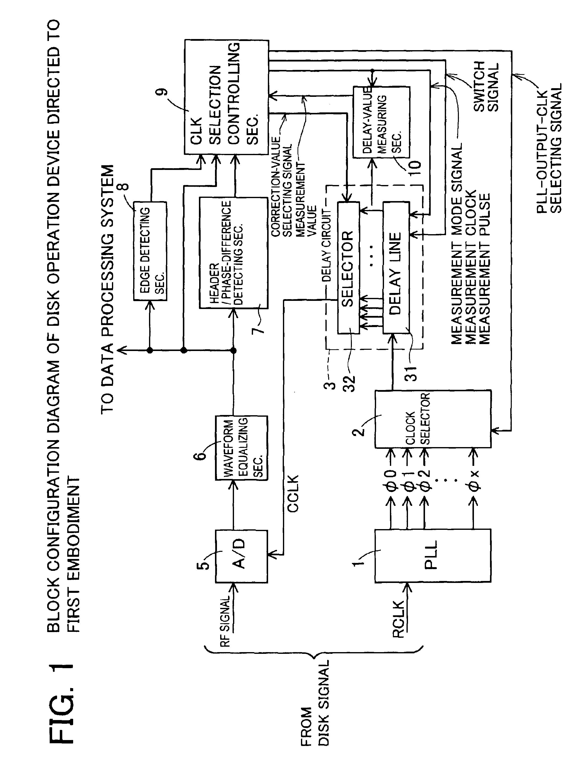
[0039]A disk operation device directed to a first embodiment is structured as shown in FIG. 1. That is, the disk operation device of this embodiment includes: a PLL 1 that receives an input of reference clock R...

second embodiment

[0062][Second Embodiment]

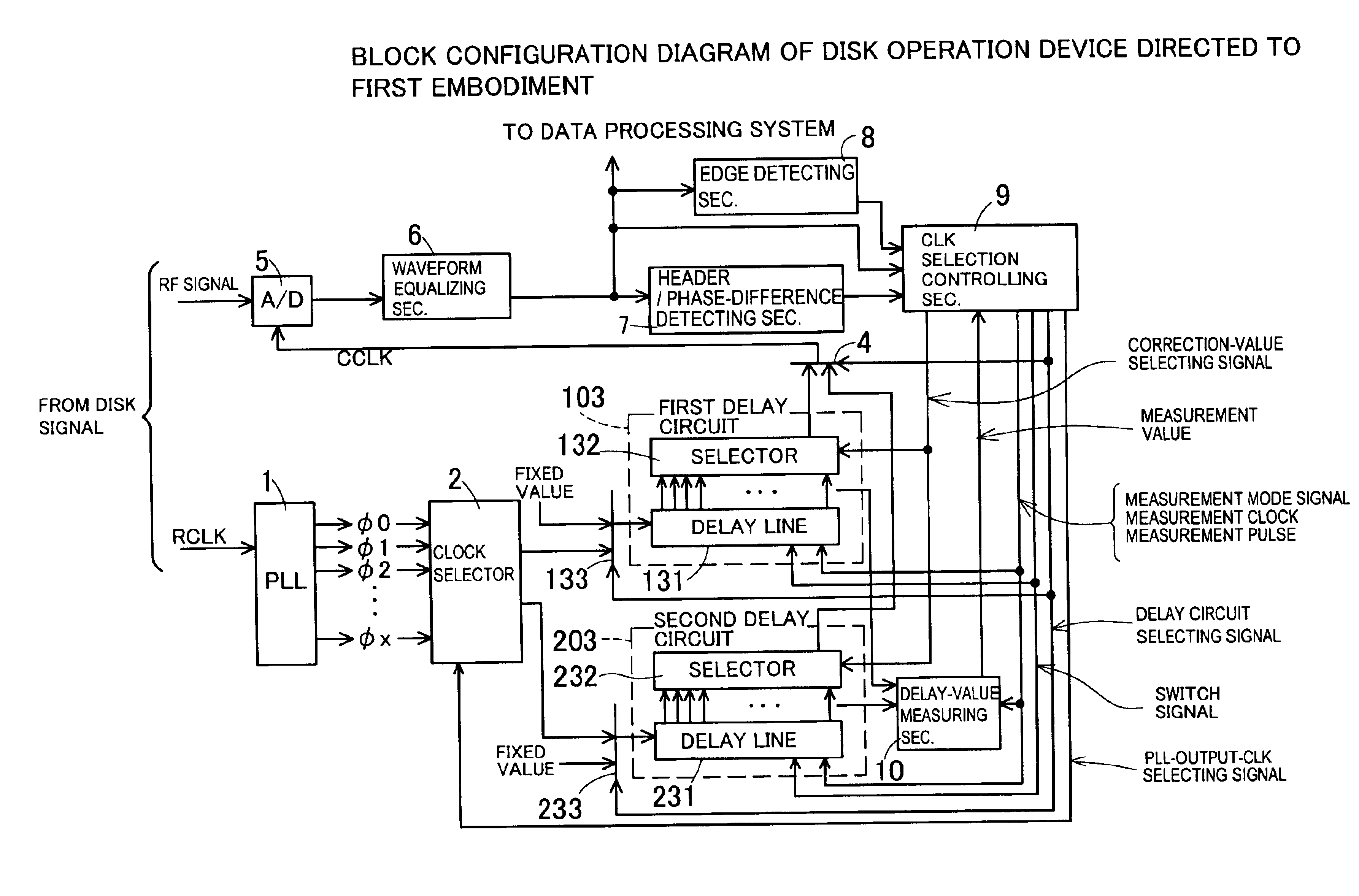
[0063]Structure of a disk operation device directed to a second embodiment is shown in FIG. 14. This disk operation device is structured such that two sets of the delay circuit for the disk operation device directed to the first embodiment are provided. That is, the disk operation device of the second embodiment includes a first delay circuit 103 and a second delay circuit 203. These delay circuits are similar to the delay circuit 3 directed to the first embodiment in terms of structure and function. The disk operation device of this embodiment selectively uses one of the two delay circuits 103 and 203. Furthermore, as described later, the delay circuits 103 and 203 are switched appropriately.

[0064]The disk operation device of this embodiment that includes two sets of delay circuit differs from the disk operation device operation directed to the first embodiment in terms of the following points. Firstly, a clock selector 2 outputs a reference clock to a dela...


PUM

PropertyMeasurementUnit
frequencyaaaaaaaaaa
phaseaaaaaaaaaa
phase-aaaaaaaaaa

Abstract

It is intended to provide a recording-medium operating device, a clock signal generating device for the recoding-medium operating device, and a method for generating a clock signal for the recoding-medium operating device that satisfy both operation with a wide-range data transfer rate using delay line provided with not so large number of stages and high correction accuracy and are advantageous in terms of low power consumption and suppression of noises. A reference clock group Ø0 through Øx different in phase are obtained by a PLL 1. One of the reference clock group is selected by a clock selector 2. A selected clock signal is inputted to a delay circuit 3 and one of output clocks from a delay line 31 is selected by a selector 3. With structure as such, selection by the clock selector 2 and the selector 3 is controlled so as to make phase difference between a clock signal and an RF signal minimum. Thereby, time equivalent to phase difference of adjoining two reference clocks is sufficient enough as total delay quantity of the delay line 31.

Description

CROSS-REFERENCE TO RELATED APPLICATIONS[0002]This application is based upon and claims the benefit of priority from each of the prior Japanese Patent Application No. 2002-248672 filed on Aug. 28, 2002, the entire contents of which are incorporated herein by reference.BACKGROUND OF THE INVENTION[0003]1. Field of the Invention[0004]The present invention relates to a recording-medium operating device and method for data operation such as data-write / data-read to recording media such as optical disks, magneto optical disks and the like used for computers, audio devices, video devices and the like and a method for operating a recording medium. More particularly, it relates to a recording-medium operating device capable of coping with a wide-range data transfer rate using delay circuit with not so large number of stages, a clock signal generating device for the recoding-medium operating device, and a method for generating a clock signal.[0005]2. Description of Related Art[0006]Data operati...

Claims


Application Information

Patent Timeline
Patent Type & Authority Patents(United States)
IPC IPC(8): G06F1/06G11B20/14G11B7/00G11B20/10G11B20/24G11B27/10
CPCG11B20/10009G11B20/10046G11B20/10425G11B20/24G11B20/10222G11B27/10
Inventor YAMAKURA, KENICHI
Owner FUJITSU LTD
Why Eureka
Try Eureka