
Mosaic arrays using micromachined ultrasound transducers

a technology of ultrasound transducer and micro-machine, which is applied in the field ofmosaic arrays of ultrasound transducer elements, can solve the problems of prohibitive volume and power consumption of electronics, the inability to easily portability of such a system, and the complex and expensive implementation of dynamically focused beams in elevation and azimuth, etc., and achieve the effect of optimal acoustic image quality

Inactive Publication Date: 2005-03-08
GENERAL ELECTRIC CO
View PDF19 Cites 161 Cited by
  • Summary
  • Abstract
  • Description
  • Claims
  • Application Information

AI Technical Summary

Benefits of technology

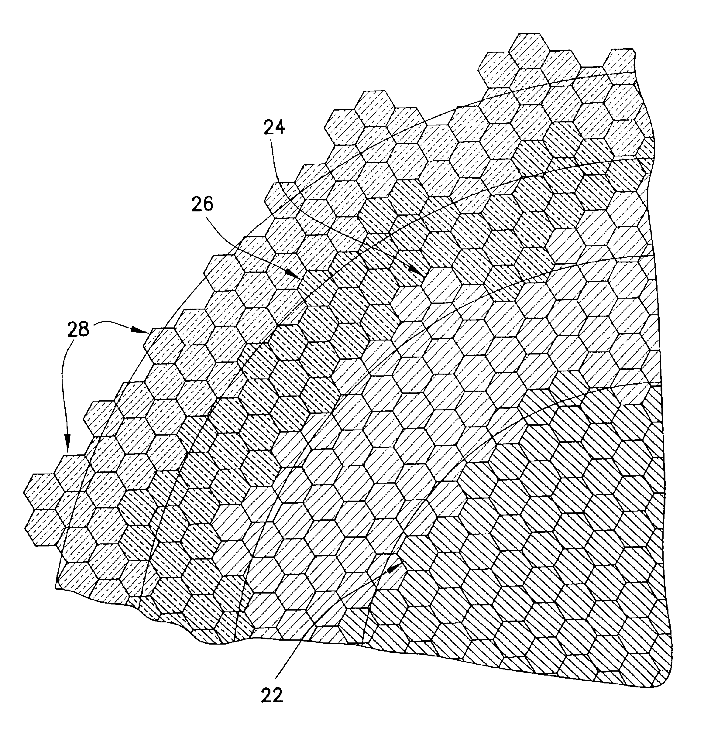
The present invention employs the idea of dividing the active aperture of an ultrasound transducer into a mosaic of very small subelements and then forming elements from these subelements by interconnecting them with electronic switches. These elements can be “moved” electronically along the surface of the mosaic array to perform scanning by changing the switch configuration. Other element configurations permit beamsteering, which will provide the ability to acquire volumetric data sets. A configuration of multiple concentric annular elements provides optimal acoustic image quality by matching the element shapes to the acoustic phase fronts. One aspect of the invention is the reconfigurability of the resulting array.
It is these capabilities to both reconfigure elements and to have elements match phase fronts that significantly reduce the number of elements (or channels) needed to achieve high-end system image quality. With fewer channels the number of signals that need to be processed by beamforming electronics is also dramatically reduced. Therefore the volume and power consumption of system electronics for a mosaic array is compatible with highly portable ultrasound systems.

Problems solved by technology

The implementation of a dynamically focused beam both in elevation and azimuth is very complex and expensive, especially for general imaging (as opposed to echocardiac) applications.
Also the volume and power consumed by the electronics is prohibitive to making such a system easily portable.

Method used


Image

  • Mosaic arrays using micromachined ultrasound transducers
  • Mosaic arrays using micromachined ultrasound transducers
  • Mosaic arrays using micromachined ultrasound transducers

Examples


Embodiment Construction

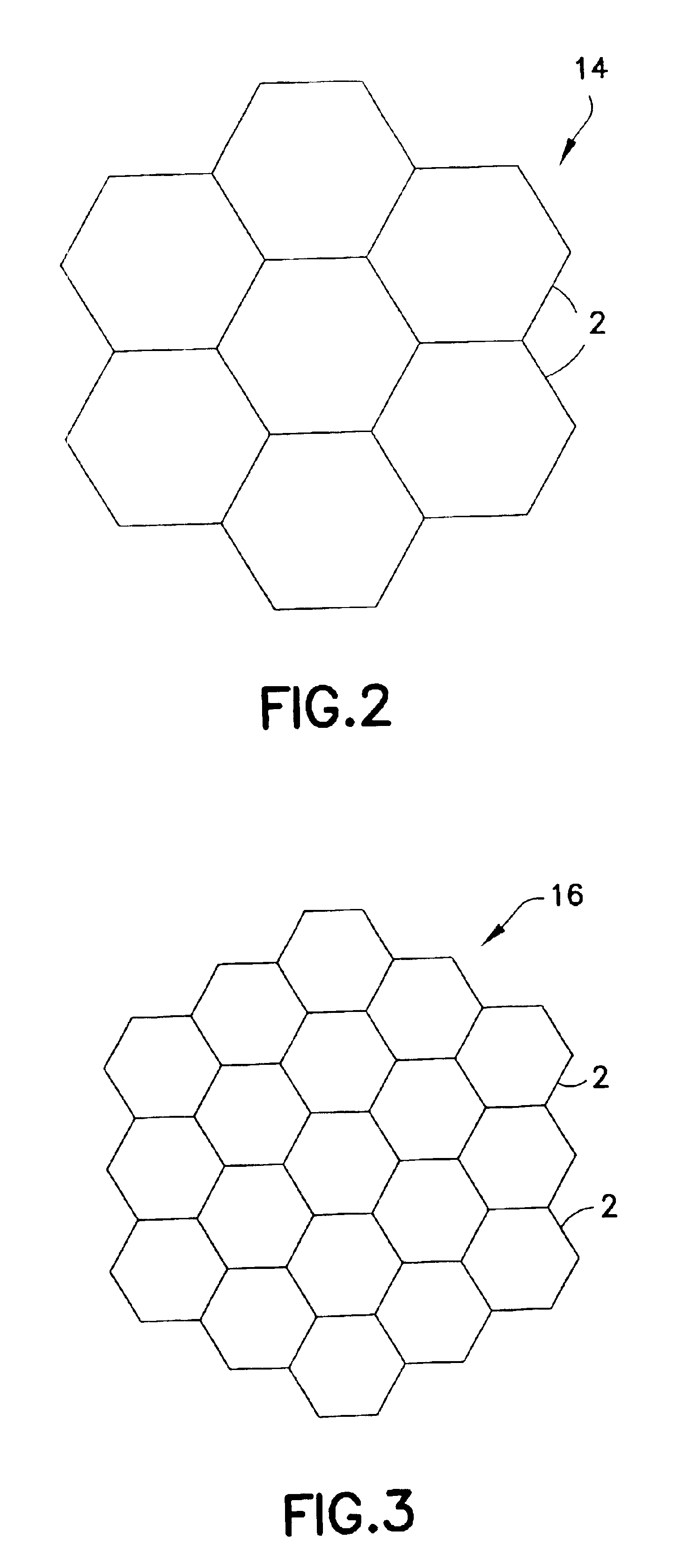
The innovation disclosed here is a unique method of implementing a mosaic array with micromachined ultrasound transducers (MUTs). For the purpose of illustration, various embodiments of the invention will be described that utilize capacitive micromachined ultrasonic transducers (cMUTs). However, it should be understood that the aspects of the invention disclosed herein are not limited to use of cMUTs, but rather may also employ pMUTs or even diced piezoceramic arrays where each of the diced subelements are connected by interconnect means to an underlying switching layer.

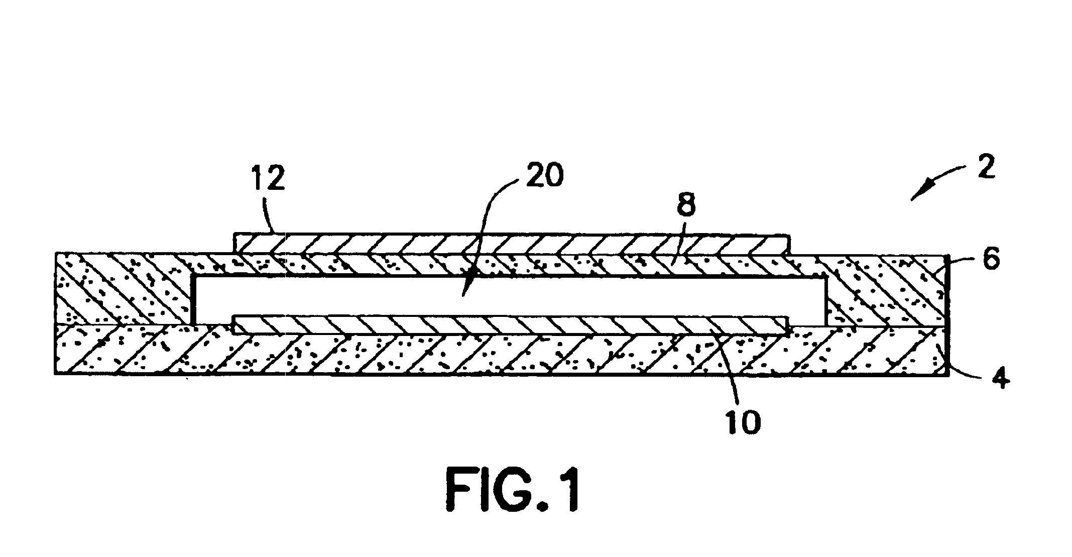
cMUTs are silicon-based devices that comprise small (e.g., 50 μm) capacitive “drumheads” or cells that can transmit and receive ultrasound energy. Referring to FIG. 1, a typical MUT transducer cell 2 is shown in cross section. An array of such MUT transducer cells is typically fabricated on a substrate 4, such as a silicon wafer. For each MUT transducer cell, a thin membrane or diaphragm 8, which may be made of silic...


PUM


Abstract

An ultrasound transducer array includes a multiplicity of subelements interconnected by a multiplicity of microelectronic switches, each subelement comprising a respective multiplicity of micromachined ultrasound transducer (MUT) cells. The MUT cells within a particular subelement are hard-wired together. The switches are used to configure the subelements to form multiple concentric annular elements. This design dramatically reduces complexity while enabling focusing in the elevation direction during ultrasonic image data acquisition.

Description

BACKGROUND OF THE INVENTIONThis invention generally relates to mosaic arrays of ultrasound transducer elements and to the use of micromachined ultrasonic transducers (MUTs) in arrays. One specific application for MUTs is in medical diagnostic ultrasound imaging systems.Conventional ultrasound imaging systems comprise an array of ultrasonic transducers that are used to transmit an ultrasound beam and then receive the reflected beam from the object being studied. Such scanning comprises a series of measurements in which the focused ultrasonic wave is transmitted, the system switches to receive mode after a short time interval, and the reflected ultrasonic wave is received, beamformed and processed for display. Typically, transmission and reception are focused in the same direction during each measurement to acquire data from a series of points along an acoustic beam or scan line. The receiver is dynamically focused at a succession of ranges along the scan line as the reflected ultraso...

Claims


Application Information

Patent Timeline
Patent Type & Authority Patents(United States)
IPC IPC(8): B06B1/06A61B8/00H10N30/00B06B1/02H04R17/00
CPCB06B1/0292E05B81/60E05B83/18E05B77/44E05Y2900/548
Inventor THOMENIUS, KAIFISHER, RAYETTE A.MILLS, DAVID M.WODNICKI, ROBERT G.HAZARD, CHRISTOPHER ROBERTSMITH, LOWELL SCOTT
Owner GENERAL ELECTRIC CO
Learn More