
Method and apparatus for directing electromagnetic radiation to distant locations

a technology of electromagnetic interference and distant locations, applied in the direction of communication jamming, instruments, measurement devices, etc., can solve the problems of affecting the operation of electronic devices, unable to produce sufficient field strength, and unable so as to achieve sufficient field strength and lower frequency interference

Inactive Publication Date: 2005-03-08
THE BOEING CO
View PDF6 Cites 62 Cited by
  • Summary
  • Abstract
  • Description
  • Claims
  • Application Information

AI Technical Summary

Benefits of technology

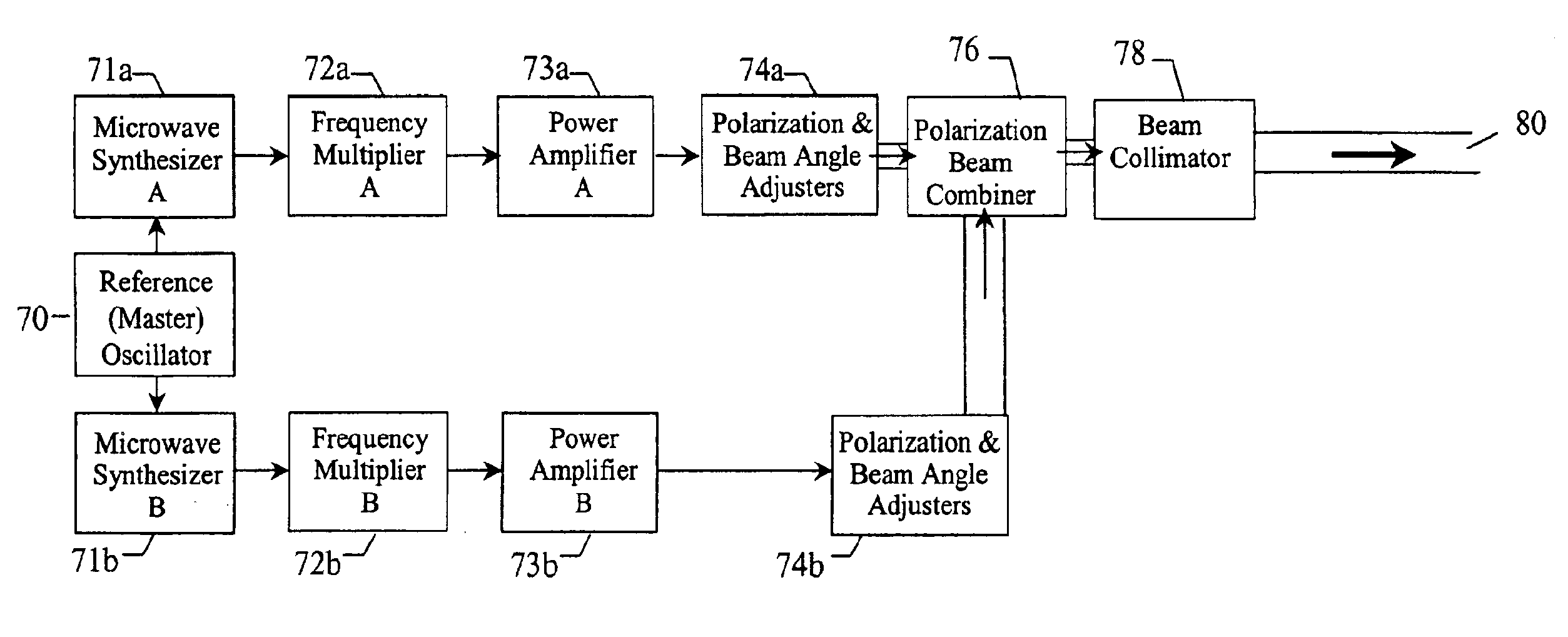
The present invention provides methods and apparatuses for creating electromagnetic interference at distant locations, thus offering a solution to the above needs. To this end, the methods and apparatuses provide an efficient way to transmit electromagnetic interference in the radio frequency region of the electromagnetic spectrum by using an interference difference frequency between two higher frequency electromagnetic beams. Therefore, the transmitted beams are easily to be collimated microwave, millimeter, or submillimeter wave radiation, yet produce lower frequency interference with sufficient field strength.

Problems solved by technology

Therefore, the transmitted beams are easily to be collimated microwave, millimeter, or submillimeter wave radiation, yet produce lower frequency interference with sufficient field strength.
For example, the interference difference frequency may be equal to a resonant frequency of an electronic device at the target, thereby interfering with the operation of the electronic device.

Method used


Image

  • Method and apparatus for directing electromagnetic radiation to distant locations
  • Method and apparatus for directing electromagnetic radiation to distant locations
  • Method and apparatus for directing electromagnetic radiation to distant locations

Examples


Embodiment Construction

The present inventions now will be described more fully hereinafter with reference to the accompanying drawings, in which some, but not all embodiments of the inventions are shown. Indeed, these inventions may be embodied in many different forms and should not be construed as limited to the embodiments set forth herein; rather, these embodiments are provided so that this disclosure will satisfy applicable legal requirements. Like numbers refer to like elements throughout.

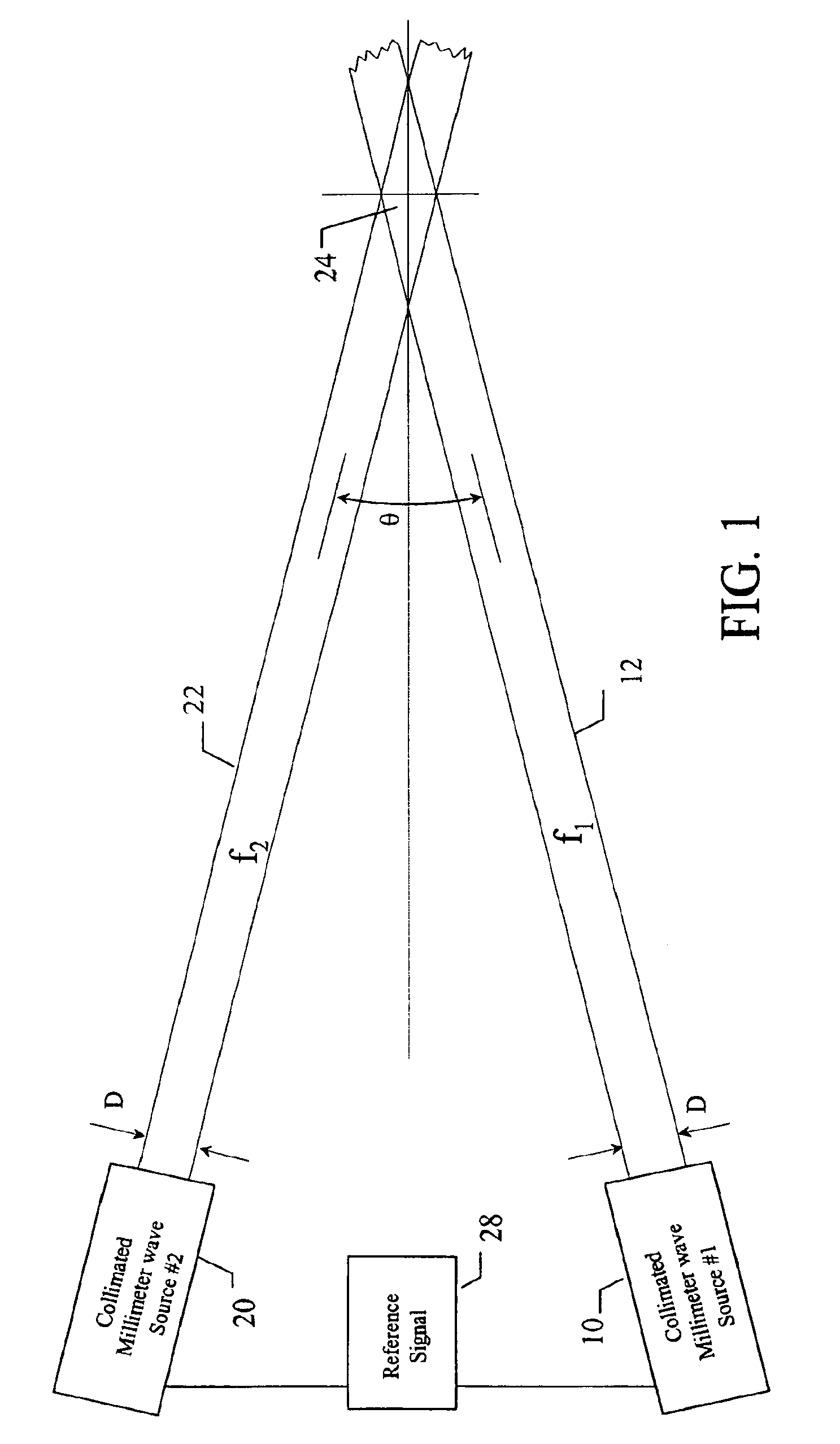
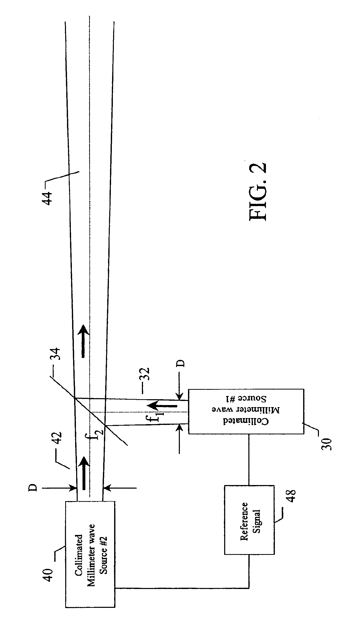
Referring to FIG. 1, two collimated millimeter wave sources 10, 20 are shown radiating collimated beams 12, 22 of electromagnetic radiation at two separate frequencies, f1 and f2, and in two intersecting directions that produce interference at a distance. Generally, when two electromagnetic beams of different frequencies converge, the volume of the intersection 24 will include a frequency component directly related to the difference in frequency of the two beams, which is defined herein as the interference differenc...


PUM


Abstract

A method of creating electromagnetic interference includes creating an electromagnetic (EM) field of a frequency at distant target by transmitting at least two electromagnetic beams. At the target, the beams may converge and interfere creating an interference difference frequency. In another method, the beams may be combined and the combined beams create an interference over a distance. An interference difference frequency is selected so that a desired electromagnetic frequency is established at the target creating interference. The interference difference frequency is established by the difference in the two electromagnetic beams. As each converges or is combined, the resultant frequency corresponds to the difference between each the frequencies of each beam. An apparatus for creating electromagnetic radiation includes at least two transmitters. The transmitters permit directing the electromagnetic beams in directions permitting either convergence of the beams or combination of the beams, thus creating electromagnetic interference.

Description

FIELD OF THE INVENTIONThe present invention relates to methods and apparatuses for creating electromagnetic interference at distant locations, and, more particularly, to a method and apparatus for creating electromagnetic interference at arbitrary radio frequencies, microwave frequencies, and millimeter wave frequencies using controlled and directed electromagnetic energy.BACKGROUND OF THE INVENTIONModern electronic circuits are, in general, very sensitive to small amounts of external electromagnetic radiation, especially, when the radiation's frequency is at or near any one of the circuit's (or circuit components') resonances. Modern circuits contain multiple layers of circuit boards and integrated circuits that include millions of transistors, diodes, and other circuit elements. These circuit elements produce miniature dipoles, monopoles, and loop antennas, which are unintentionally created when the circuits were laid down.The combination of these parts result in a very large numb...

Claims


Application Information

Patent Timeline
IPC IPC(8): H04K3/00
CPCH04K3/42H04K2203/32H04K3/44H04K3/43F41H13/0068F41H13/0075
Inventor HOLLY, SANDOR
Owner THE BOEING CO
Learn More