Fuel pre-heating device

a preheating device and fuel technology, applied in the direction of combustion types, lighting and heating apparatuses, roads, etc., can solve the problems of large waste of gas, inability to make a small configuration, and the device itself is expensive to manufacture, so as to increase the fuel efficiency and reduce the cost of production. , the effect of small configuration

Inactive Publication Date: 2005-03-08
PURCELL BRENT
View PDF5 Cites 2 Cited by
  • Summary
  • Abstract
  • Description
  • Claims
  • Application Information

AI Technical Summary

Benefits of technology

The present invention discloses a fuel pre-heating device for use with gas heaters to increase fuel efficiency that can be made into a small configuration and is inexpensive to manufacture. The fuel pre-heating device of the present invention comprises an orifice and a pre-heat tube. The pre-heating device can be easily added to standard heaters. The fuel enters the device through the orifice and travels through the pre-heat tube and back to the orifice where it is then expelled. Upon exit from the orifice and tube, the fuel mixes with air and forms a flame that envelopes the entire pre-heat tube and heats the fuel within the tube to a very high temperature. Any air mixer known to those skilled in the art can be used with the heating tube. A heat conductor can also be used with the pre-heat tube.
The small size of the heating tube allows for immediate preheating of the fuel, which is used by the heater in the same heating cycle, thereby yielding a more efficient preheat. This preheating system prevents the fuel from being wasted. The fuel efficiency improvement using a gas burner equipped with the pre-heating device of the present invention is in the range of 10-36% over the standard gas heater.

Problems solved by technology

However, a problem with gas heaters is that not all gas is burned by the heaters, and, therefore, much gas is simply wasted.
While this device does pre-heat the fuel, the device itself is expensive to manufacture and cannot be made into a small configuration.

Method used


Image

  • Fuel pre-heating device
  • Fuel pre-heating device
  • Fuel pre-heating device

Examples


Embodiment Construction

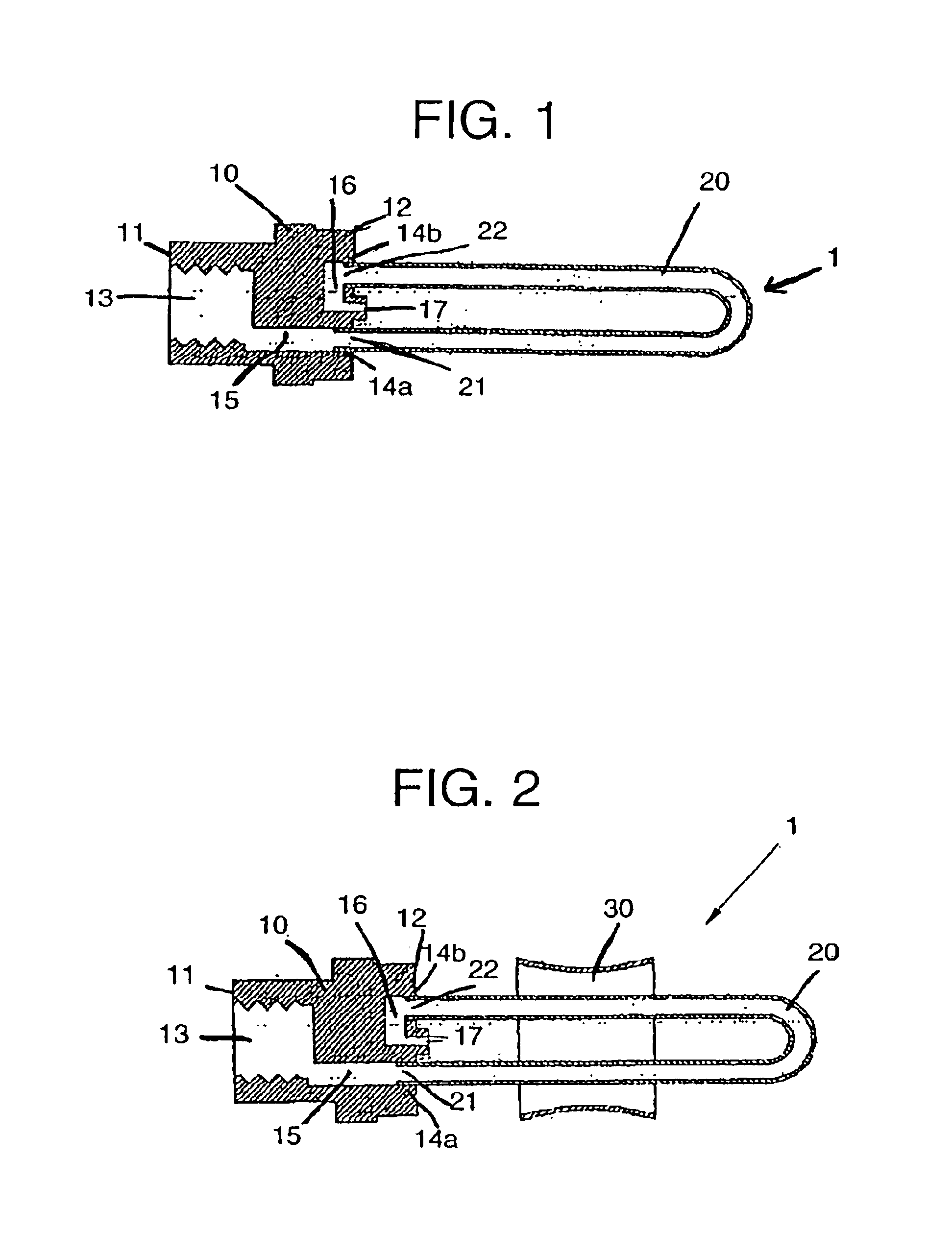
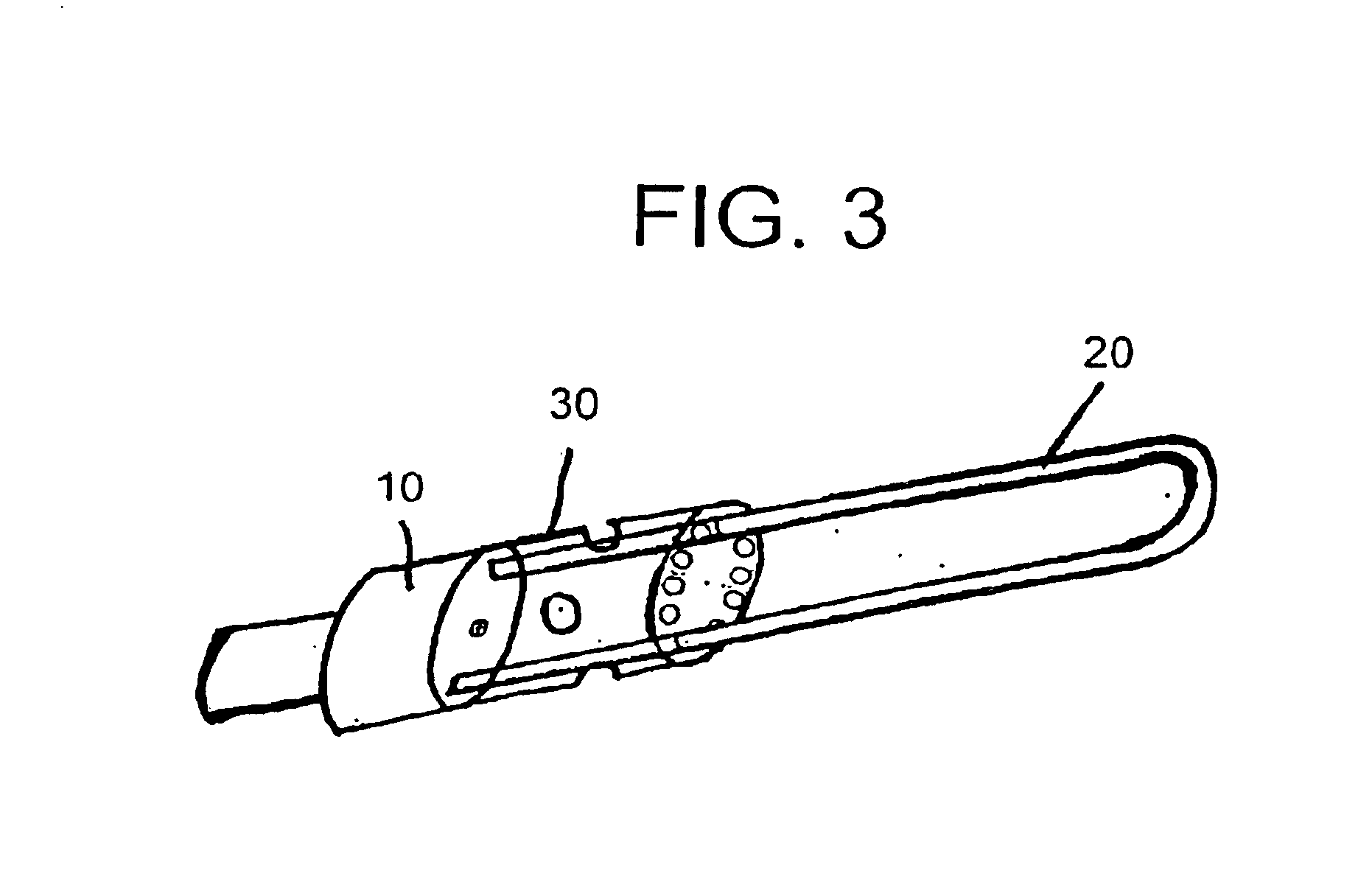
The fuel pre-heating device 1 of the present invention comprises an orifice 10 and a pre-heat tube 20. The pre-heating device is easily added to standard heaters that use natural gas, propane, or other low carbon fuel by simply removing the standard fuel exit orifice and attaching the orifice of the pre-heating device.

As shown in FIG. 1, orifice 10 has a first end 11 and second end 12. First end 11 has a threaded recess 13 for connecting to a heater, and second end 12 has attachment points 14a and 14b for receiving pre-heat tube 20. Attachment point 14a receives first end 21 of pre-heat tube 20 while attachment point 14b receives second end 22 of pre-heat tube 20. Fuel enters fuel pre-heating device 1 at recess 13 and flows through cavity 15 of orifice 10 and into first end 21 of pre-heat tube 20 as shown in FIG. 1. The fuel flows through the entire pre-heat tube 20 and back into second end 12 of orifice 10 where it is forced through cavity 16 and out of orifice 10 at opening 17.

Upo...


PUM


Abstract

A fuel pre-heating device for use with gas heaters to increase fuel efficiency including an orifice and a pre-heat tube. Fuel enters the device through the orifice and travels through the pre-heat tube and back to the orifice where it is then expelled and mixed with air to ignite into a flame that envelopes the entire pre-heat tube and heats the fuel within the lube to a very high temperature. Any air mixer known to those skilled in the art can be used with the heating tube. A heat conductor can also be used with the pre-heat tube. The pre-heating device can be easily added to standard heaters, is small in configuration, and inexpensive to manufacture. The small size of the heating tube allows for immediate preheating of the fuel, which is used by the heater in the same heating cycle, thereby yielding a more efficient preheat. This preheating system prevents the fuel from being wasted.

Description

BACKGROUND OF INVENTIONGas heaters are extremely popular heating devices. Gas heaters are now safe, environmentally friendly, and economically sensible. However, a problem with gas heaters is that not all gas is burned by the heaters, and, therefore, much gas is simply wasted. There is potential for gas heaters to be more fuel-efficient.One method for increasing fuel efficiency is pre-heating fuel. Previous fuel pre-heating mechanisms include running fuel through a long coiled tube that forms a cylinder. A flame is shot through the hollow center of the coiled cylinder which heats the fuel inside the tube. While this device does pre-heat the fuel, the device itself is expensive to manufacture and cannot be made into a small configuration. Other pre-heating mechanisms heat the tube, but specifically protect the tubes in order to prevent the tubes from getting extremely hot. Still other pre-heating devices heat the fuel but then allow a cooling off period before the fuel is actually us...

Claims


Application Information

Patent Timeline
Patent Type & Authority Patents(United States)
IPC IPC(8): F23D11/36F23D11/44
CPCF23D14/66F23D11/443Y02E20/34
Inventor PURCELL, BRENT
Owner PURCELL BRENT
Why Eureka
Try Eureka