Collapsible serving tray

a serving tray and collapsible technology, applied in the field of food and beverage service, can solve the problems of poor rigidity, difficult storage, and large size of traditional trays, and achieve the effects of preserving rigidity across the joint, sufficient rigidity, and improving shear strength

Inactive Publication Date: 2006-03-09
D OLIMPIO DOMINIC
View PDF4 Cites 7 Cited by
  • Summary
  • Abstract
  • Description
  • Claims
  • Application Information

AI Technical Summary

Benefits of technology

[0007] It is therefore an object of the invention to provide a rigid serving tray surface. It is another object of the invention to provide a rigid serving tray that can be folded into a much smaller configuration for storage. It is a further object of the invention to provide a foldable tray that can be deployed and returned to a storage configuration quickly and easily, preferably with one hand. It is yet another object of the invention to provide a tray that is aesthetically pleasing and that optionally provides advertising space on its surfaces. SUMMARY OF THE INVENTION
[0009] The four quadrants are also attached to one another on the opposite side from the hinges by a flexible material, for example rubber or rubber-like silicone. The two quadrants that are unhinged are therefore attached to one another by the flexible material. In this embodiment, the position of the hinges and the number of joints allow the tray to fold down to the size of one quadrant that is four layers thick. This size enables a server to store the tray in a pocket or apron, or clip it to a belt, or tuck it into the small of the back. The flexible material is positioned and configured that it is stretched when the tray is folded into its storage configuration. Thus the flexible material pulls the quadrants into the flat unfolded position.
[0011] The mechanism that provides the stiffness of this embodiment of the tray is the function of the edge portions when they are hinged ninety degrees to the flat serving surface. These small edge portions when folded up and reversibly locked together produce a stiffening beam effect across the hinge areas of the four quadrants enabling the flexible joint of the fold to become stiff when the tray is open. The one unhinged joint of the quadrants needs to be locked when the tray is open. This is achieved by a locking mechanism to secure the walls bent ninety degrees and joined across the open quadrant. Other stiffening features include a tongue and groove detail in the edge of the quadrants that are not hinged. This feature improves the shear strength in the open position.
[0012] Two mechanisms that provide features for ease of opening and closing can be used in slightly different embodiments. In one embodiment, a spring-tensioned system is employed to connect the perimeter walls. This spring mechanism enables the side walls to move from being planner with the four quadrants to ninety degrees to the quadrants plane, in one simultaneous action. This action also engages a snap mechanism on the unhinged side which secures the tray's integrity. In another embodiment, the spring-tensioned system is replaced by a circumferential elastomeric loop that connects the perimeter walls. The second mechanism is the use of an elastomeric surface that provides the features of self opening the tray as well as maintaining a lateral force on the unhinged quadrant joints to preserve the stiffness across the joint.

Problems solved by technology

Traditional trays are too large to carry in a pocket or apron and are difficult to store when servers need to write or use their hands in serving.
They exhibit good stiffness in serving but not easy storing and carrying.
Existing folding trays made of paper and cardboard exhibit good storage properties at minimum expense but do not prove sturdy enough in service or provide stiff enough service surfaces, especially for repeated use.

Method used


Image

  • Collapsible serving tray
  • Collapsible serving tray
  • Collapsible serving tray

Examples


embodiment 1

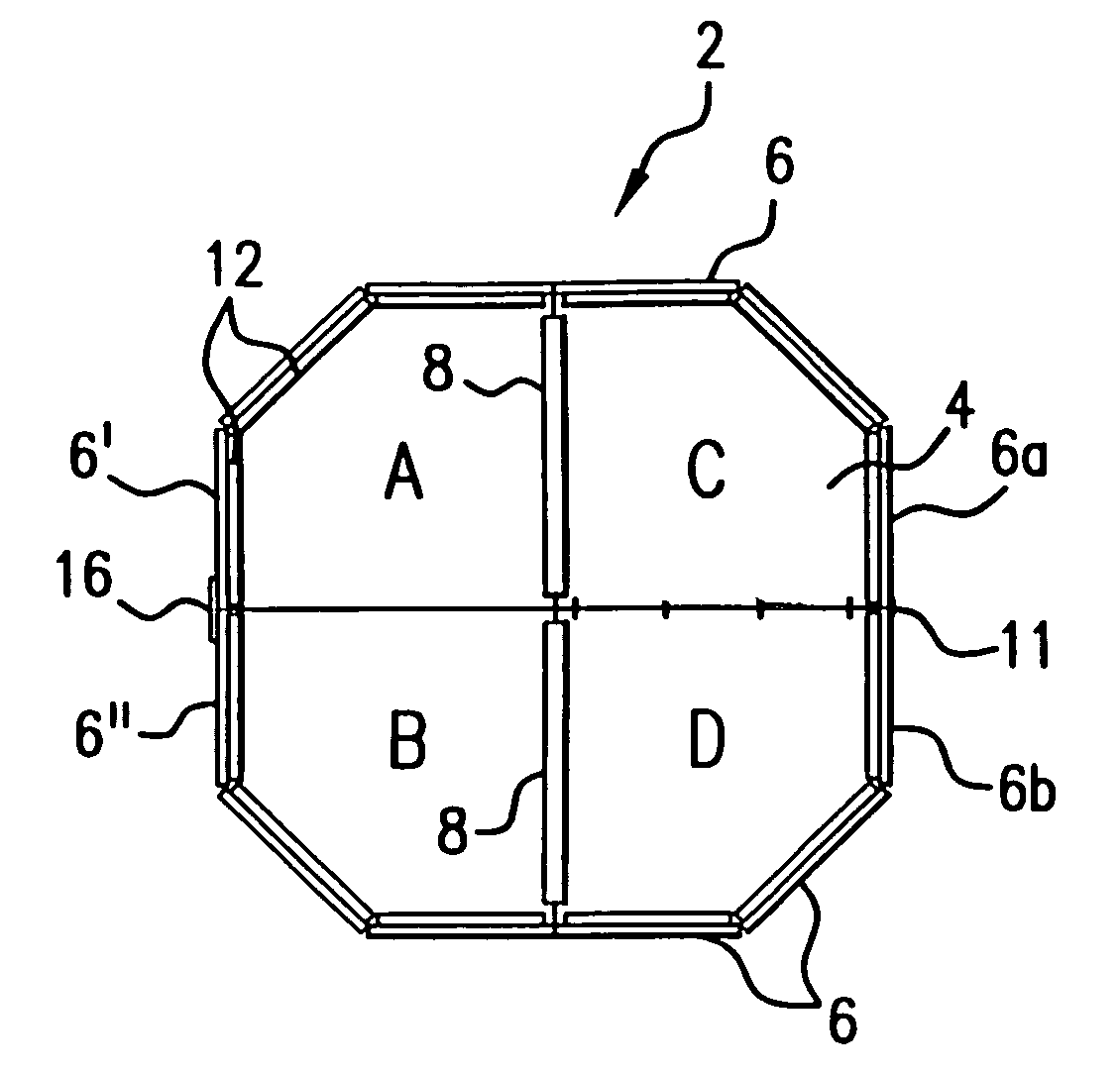
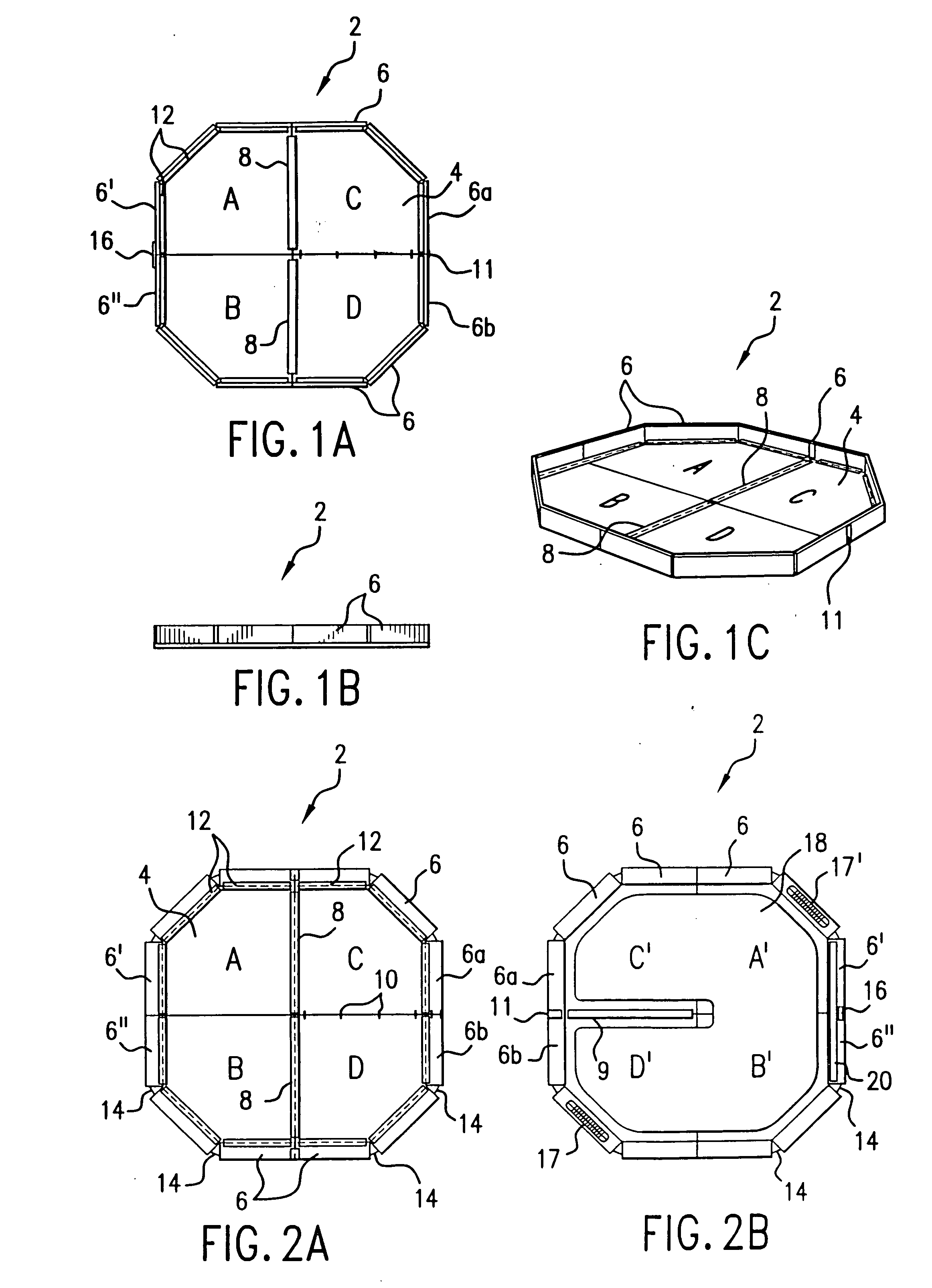
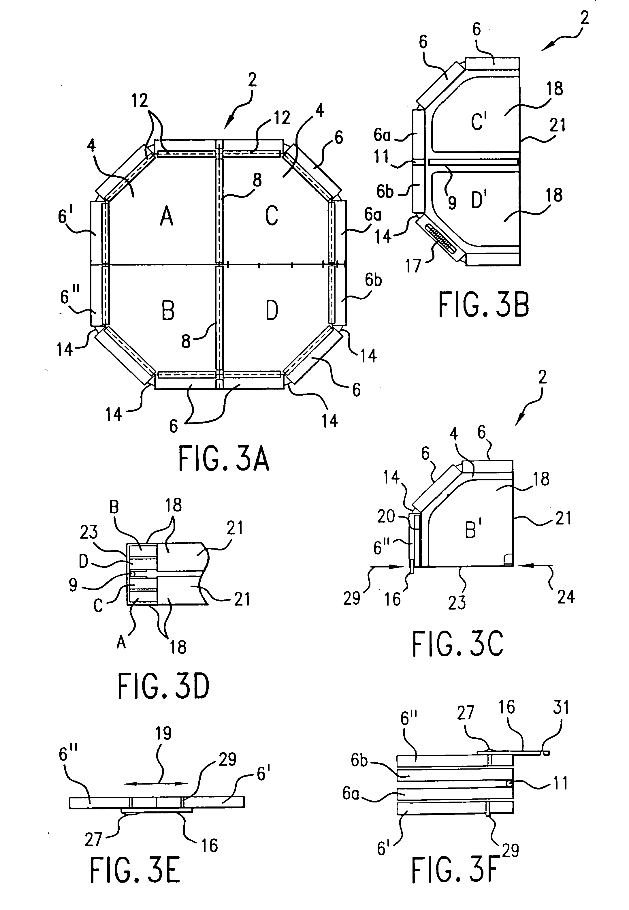
[0182] Referring to FIGS. 1A, 1B and 1C, the folding tray 2 according to the present invention is shown in orthogonal top view and side views respectively. FIG. 1C shows the tray 2 in an oblique view. As shown in FIG. 1A, the flat base portion 4 of the octagonal folding tray 2 comprises four quadrants that are labeled A, B, C and D in the figure, a labeling convention that has been chosen as an aid in describing the novel method by which the tray is folded to one quarter of its fully deployed, in-service size. In FIG. 1A, quadrant A of the base portion 4 is joined to the quadrant C by a hinge 8, and the quadrant B is the also joined by a another hinge, also denoted by 8, to the quadrant D. Quadrants C and D are also joined by a hinge. The edge portions 6 of the tray are visible in both the top and side views. In this embodiment, the edge portions 6 comprise a plurality of components, in this embodiment 12, which are connected by hinges 12 (only representative hinges identified in th...

embodiment 2

[0189] A second embodiment of a folding tray 3, in rectangular form, is shown in top view in FIG. 4A. In this embodiment, there are no vertical edges around the perimeter, as in the first embodiment. A side view of the tray 3 is shown in FIG. 4B, wherein are visible in respective straight-on and side views two latching mechanisms 30a and 30b. FIG. 4C shows the bottom side of the base portion 32.

[0190] When the three latching mechanisms 30a, 30b and 30c are oriented such that the planes of the latching mechanisms are each more or less perpendicular to the plane of the base portion 32, they maintain the base portion, which is comprised of four quadrants labeled W, X, Y and Z, in a rigid and flat deployed position that is fully usable as a tray of the sort used to carry drinks in a restaurant. The three two-part latching mechanisms 30a, 30b and 30c are connected to the base portion 32 by respective hinges 34a, 34b and 34c. Each of the three latching mechanisms also has hinge portions ...


PUM


Abstract

A collapsible serving tray that is stiff and flat when open and reduced in size and compact when folded. The tray is designed to be folded up into a compact size that is about one-quarter of the fully deployed size of the tray. One embodiment of the tray includes a perimeter edge that is ninety degrees to the flat serving surface when the tray is fully deployed.

Description

PRIORITY [0001] This application is a divisional of and claims priority from U.S. patent application Ser. No. 10 / 282,355, filed Oct. 29, 2002.BACKGROUND OF INVENTION [0002] 1. Field of Invention [0003] The present invention relates to the service of food and beverages. In particular, it relates to trays upon which to deliver such items. It further relates to serving trays which can be deployed quickly and returned to storage quickly. More particularly, the invention relates to a sturdy serving tray capable of being reusably folded into a small manageable size that fits into a pocket or holster and then reversibly deployed into a rigid tray which can carry a plurality of, e.g., beverage containers. The invention further relates to a multi-folding mechanism that enables an assembly to be both flexible and stiff in its desired modes of use. [0004] 2. Background of the Invention [0005] Serving trays have been used since time out of mind in food and beverage service to assist the server ...

Claims


Application Information

Patent Timeline
Patent Type & Authority Applications(United States)
IPC IPC(8): B65D6/12A47G23/06B65D1/34B65D6/04B65D6/18
CPCB65D7/08B65D11/1833B65D11/10B65D7/26
Inventor D'OLIMPIO, DOMINIC M.SANTIN, ANDREW W.
Owner D OLIMPIO DOMINIC
Why Eureka
Try Eureka