Side sliding door apparatus for electric railcar

a technology for sliding doors and electric railcars, applied in the direction of locking applications, wing accessories, transportation and packaging, etc., can solve the problems of difficult to securely unlock the sliding doors, difficult to recognize, and tend to have a play

Inactive Publication Date: 2005-03-08
FUJI ELECTRIC CO LTD
View PDF11 Cites 14 Cited by
  • Summary
  • Abstract
  • Description
  • Claims
  • Application Information

AI Technical Summary

Benefits of technology

[0026]It is possible to provide means for detecting an operation of the emergency handle. The detecting means transmits an operation signal to shut off power supply to an actuator so that the sliding doors can open and close manually. Thus, it becomes easy and safe to manually open the unlocked sliding doors.

Problems solved by technology

The above described side sliding door apparatus for the electric railcar disclosed in the patent publication turned out to have problems as described below.
The cable wire, however, tends to have a play due to tension or loosening, and therefore it is difficult to securely unlock the sliding doors.
Thus, it is difficult to recognize that the sliding doors can be opened manually, thereby delaying for the passengers to quickly go out of the electric railcar.

Method used


Image

  • Side sliding door apparatus for electric railcar
  • Side sliding door apparatus for electric railcar
  • Side sliding door apparatus for electric railcar

Examples


first embodiment

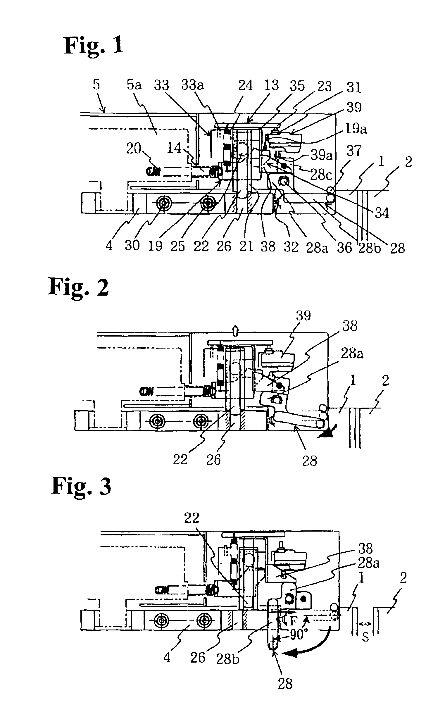
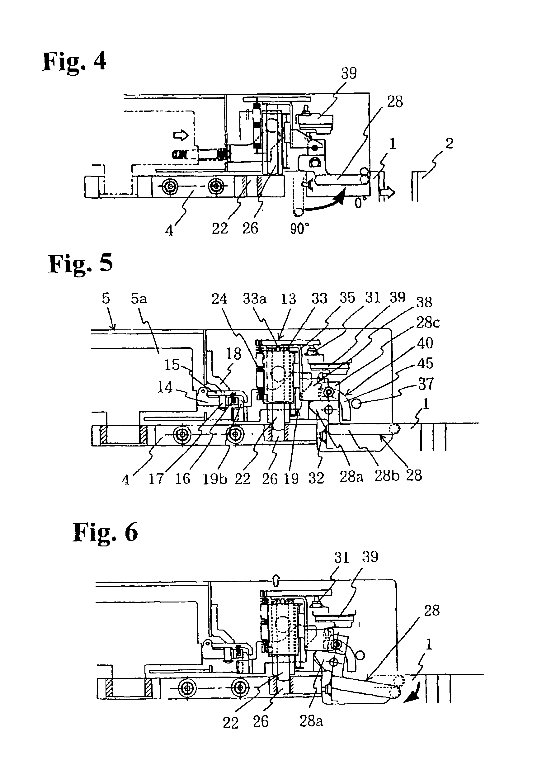
[0040]Hereunder, embodiments of the invention will be explained with reference to the accompanying drawings. FIGS. 1 to 4 show a sliding door apparatus for an electric rail car according to the present invention. Elements and parts corresponding to those of the conventional door apparatus shown in FIGS. 10 to 13 are denoted by the same reference numerals.

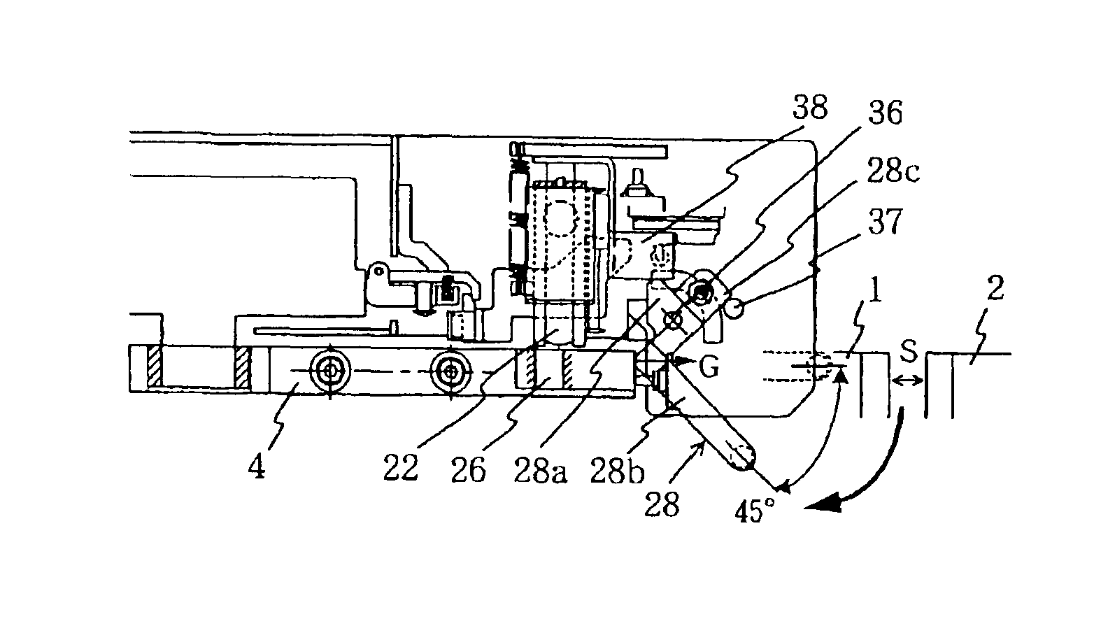
[0041]FIG. 1 is a side view showing essential parts of the side sliding door apparatus in a locked state. In FIG. 1, as is the case with the prior art, two sliding doors 1, 2 are suspended via moving bodies 4 from a door rail (not shown) mounted horizontally along a side of an electric railcar. The two sliding doors move horizontally in reverse directions in FIG. 1 to open and close an entrance of the electric railcar.

[0042]A linear motor 5 as an actuator for opening and closing the sliding doors 1, 2, a locking mechanism for locking the closed sliding doors 1, 2, and an unlocking mechanism for unlocking the sliding doors 1, 2 are p...

second embodiment

[0055]Specifically, in the unlocked state in FIG. 3, the flat end face of the cam part 28a of the emergency handle 28 contacts the lower surface of the unlock arm 38. Also, the center of the contact surface between the cam part 28a and the unlock arm 38 in the horizontal direction in FIG. 3 is located just above an axis 36 that is a pivot of the emergency handle 28. Therefore, in order to rotate the emergency handle 28 counterclockwise, the unlock arm 38 must be pushed up against the force of the lock spring 24, thereby creating a large resistance. The handle 28b contacts the end face of the moving body 4 in parallel as well. Therefore, when the moving body 4 collides with the handle 28b, an application point of an impact force F is not constant. Assuming that the impact force F is applied to the handle 28b at a top end face of the moving body 4 as shown in FIG. 3, an arm length of the rotational moment around the axis 36 is small, thereby making it difficult to rotate the emergency...


PUM


Abstract

A sliding door apparatus has a sliding door movably supported on a horizontal door rail for opening and closing an entrance of a vehicle, i.e. railroad car. The sliding door is locked when a latch member engages a fixing member disposed on the sliding door. When an emergency handle is operated, the latch member is released from the fixing member, and the sliding door can be opened manually. A motion of the emergency handle is directly transmitted to the latch member to release the latch member from the fixing member. Therefore, it is possible to operate the sliding door reliably without a problem associated with the flexible wire.

Description

BACKGROUND OF THE INVENTION AND RELATED ART STATEMENT[0002]The present invention relates to a side sliding door apparatus having sliding doors for opening and closing an entrance at a side of an electric railcar.[0003]For protecting passengers in an electric railcar, a side sliding door apparatus is required to have such a high reliability without any accidental operation while the railcar is running or staying stationary. In case of emergency, however, the side sliding door apparatus is required to be opened quickly by a simple operation. To this end, the inventors of the present application have developed a side sliding door apparatus for an electric railcar disclosed in Japanese Patent Publication (TOKKAI) No. 2000-142392.[0004]FIG. 10 to FIG. 13 show the side sliding door apparatus for the electric railcar disclosed in the patent publication, and a brief description thereof will be given. FIG. 10 is a side view showing an entire structure of the side sliding door apparatus for t...

Claims


Application Information

Patent Timeline
Patent Type & Authority Patents(United States)
IPC IPC(8): B61D19/00B61D19/02E05B65/08E05F15/14E05B47/00E05B65/10E05B83/02E05B83/36
CPCB61D19/02E05B65/08E05B47/00E05F17/004E05F15/655E05Y2201/246E05Y2201/434E05Y2900/51E05Y2800/73E05Y2201/22
Inventor INAGE, AKIO
Owner FUJI ELECTRIC CO LTD
Why Eureka
Try Eureka