
Profile-driven data layout optimization

Inactive Publication Date: 2005-03-01
MICROSOFT TECH LICENSING LLC
View PDF19 Cites 52 Cited by
  • Summary
  • Abstract
  • Description
  • Claims
  • Application Information

AI Technical Summary

Benefits of technology

The invention includes a method and system for data layout optimization based on profiling. Various features provided by the system lead to better use of resources and improved performance. For example, data members of a software object can be divided into separate groups. Further, the system can provide feedback to assist in re-designing software object classes.
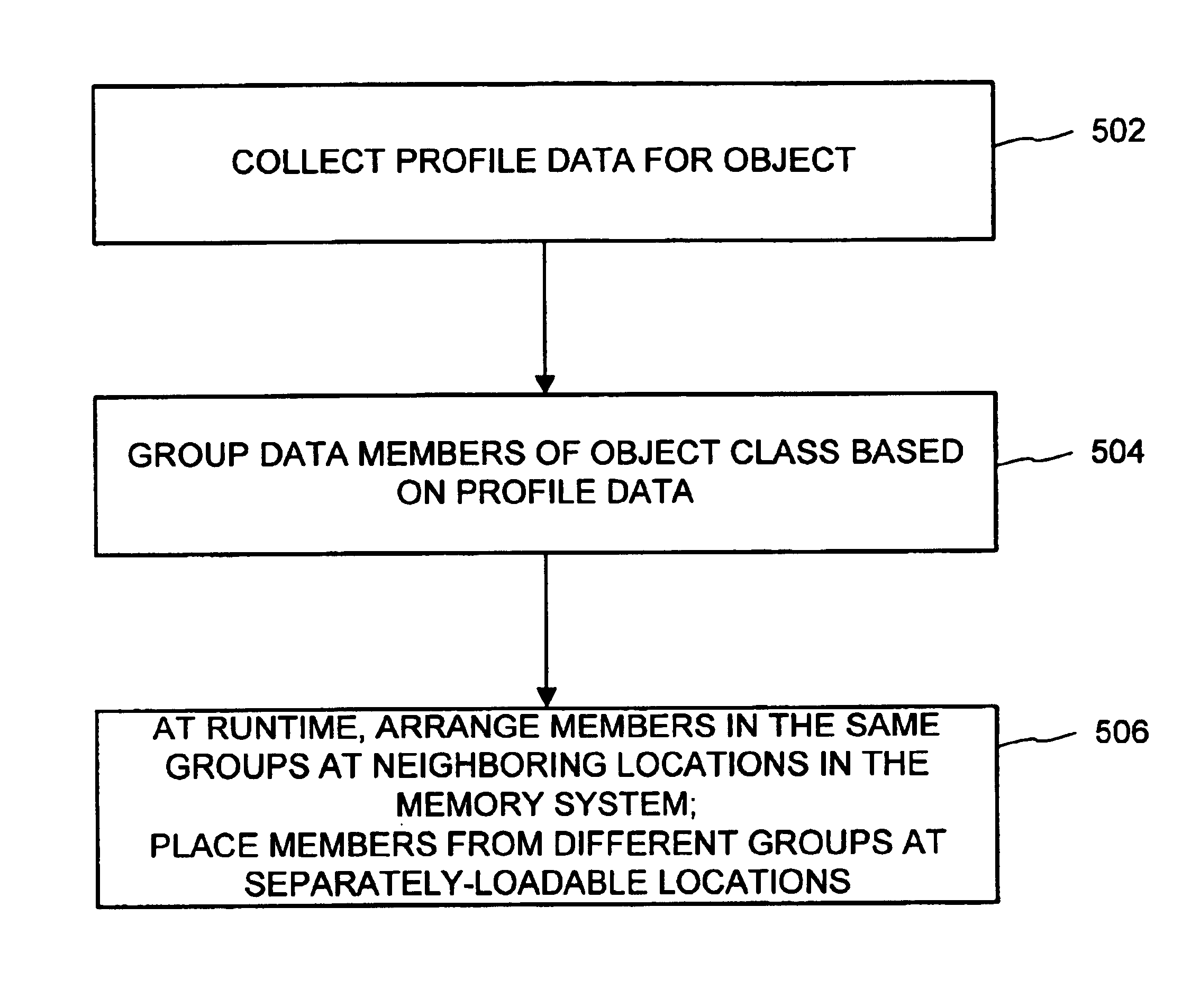
In one feature, data members of an object can be split into plural separate groups. For example, some data members of an object class can be designated as residing in a hot group, while others reside in a cold group. At runtime, the groups can be placed in separately-loadable units of a memory system. Data members from the same group can be placed at neighboring locations in the memory system. From the perspective of functions within the software, the division of the data members is inconsequential, but software performance can be improved.
In yet another feature, calculations for determining layout of data include the time domain to determine affinity of data members of one another with respect to time. Thus, “affinity” in such an arrangement means affinity in time. Analysis of the observation of software's behavior can determine that certain data members tend to be referenced at times close to each other. As a result of making such a determination, the data members can be placed close to each other in the memory system. Affinity-based layout can produce better results under certain circumstances.
Various aspects of the invention thus improve upon the above-described optimization technique, which focuses on optimizing the arrangement of data members of an object. The problem referred to as “dragging around dead data” is avoided. Performance is increased dramatically under certain circumstances, such as when some data members are quite frequently referenced, while others are referenced only a few times, once, or not at all.

Problems solved by technology

While the above-described techniques can lead to significant improvements in software performance, they focus on the code-related portions of software and fail to recognize inefficiencies related to the data-related portions of software.
These techniques further fail to take into account various peculiarities of object-oriented software.

Method used


Image

  • Profile-driven data layout optimization
  • Profile-driven data layout optimization
  • Profile-driven data layout optimization

Examples


Embodiment Construction

The invention is directed toward a method and system for laying out data members of software objects. In one embodiment illustrated herein, the invention is incorporated into a runtime environment associated with the “COM+” component of an operating system entitled “MICROSOFT WINDOWS 2000,” both marketed by Microsoft Corporation of Redmond, Wash. Briefly described, this software is a scaleable, high-performance network and computer operating system providing an object execution environment for object programs conforming to COM and other specifications. COM+ also supports distributed client / server computing. The COM+ component incorporates new technology as well as object services from prior object systems, including the MICROSOFT Component Object Model (COM), the MICROSOFT Distributed Component Object Model (DCOM), and the MICROSOFT Transaction Server (MTS).

Exemplary Operating Environment

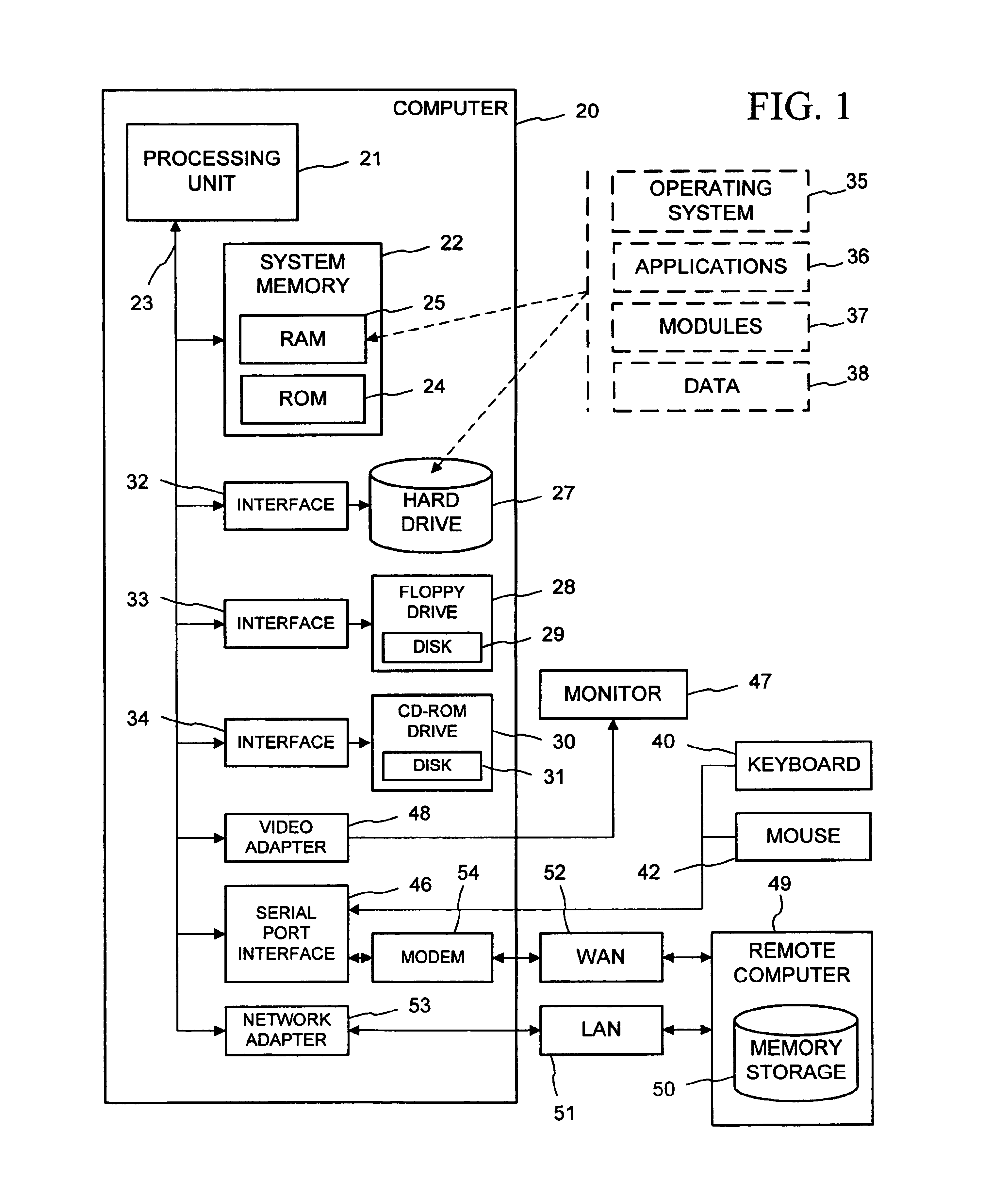
FIG. 1 and the following discussion are intended to provide a brief, general description of a su...


PUM


Abstract

Data layout optimization arranges data members within memory to enhance software performance. Profiling data is consulted to determine how to group data members for an object class into groups. One technique groups the data members based on how frequently the data members are referenced in memory. Another technique groups the data members based on their affinities for one another in time as determined by observing when references to the data members take place. A variety of options when collecting the profiling data and grouping the data members is supported. The data member grouping is recorded in metadata associated with a definition of the object class. At runtime, a class loader places the data members of an object in memory according to the metadata. Data members of different groups can be placed in separately-loadable units of memory in the memory system. Subsequently, when the data members are referenced in memory, more frequently referenced data members, including those that tend to be referenced at times close to each other, reside at neighboring locations in the memory system.

Description

TECHNICAL FIELDThe invention relates to optimization of computer software, and more particularly relates to determining data layout based on data obtained by profiling the software.BACKGROUND OF THE INVENTIONVarious techniques have evolved for improving the performance of computer software. A category of techniques commonly called “optimization” evaluates a piece of software and modifies its operation to improve performance while preserving the software's functionality.For example, the architecture of many computer systems organizes memory into pages. Such systems may include a mechanism by which a limited number of pages can be loaded into primary memory for access by a processor. Additional pages can be stored in secondary memory; however, when the system accesses secondary memory, processing is suspended while moving the pages from secondary memory to primary memory.For purposes of illustration, consider a piece of software having instructions for four procedures A, B, C, and D e...

Claims


Application Information

Patent Timeline
IPC IPC(8): G06F9/445G06F9/44
CPCG06F9/44557G06F9/445G06F9/4428G06F9/4488
Inventor KUCH, GERALD DWAYNEBECKMAN, BRIAN C.ZANDER, JASON L.
Owner MICROSOFT TECH LICENSING LLC
Learn More