Electric blower
- Summary
- Abstract
- Description
- Claims
- Application Information
AI Technical Summary
Benefits of technology
Problems solved by technology
Method used
Image
Examples
embodiment 1
(Embodiment 1)
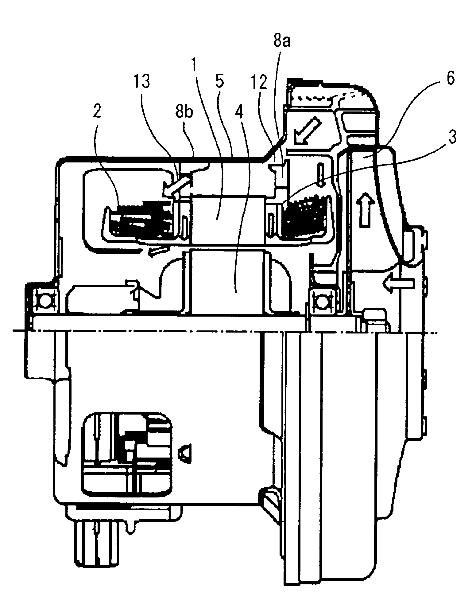
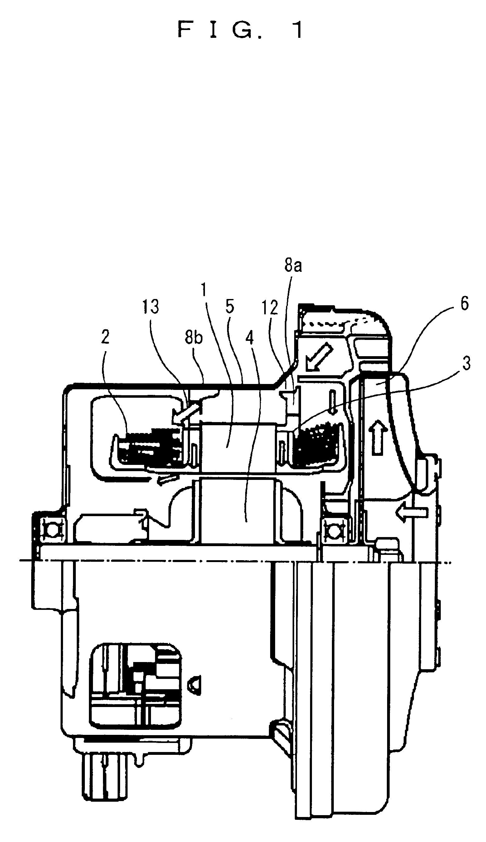
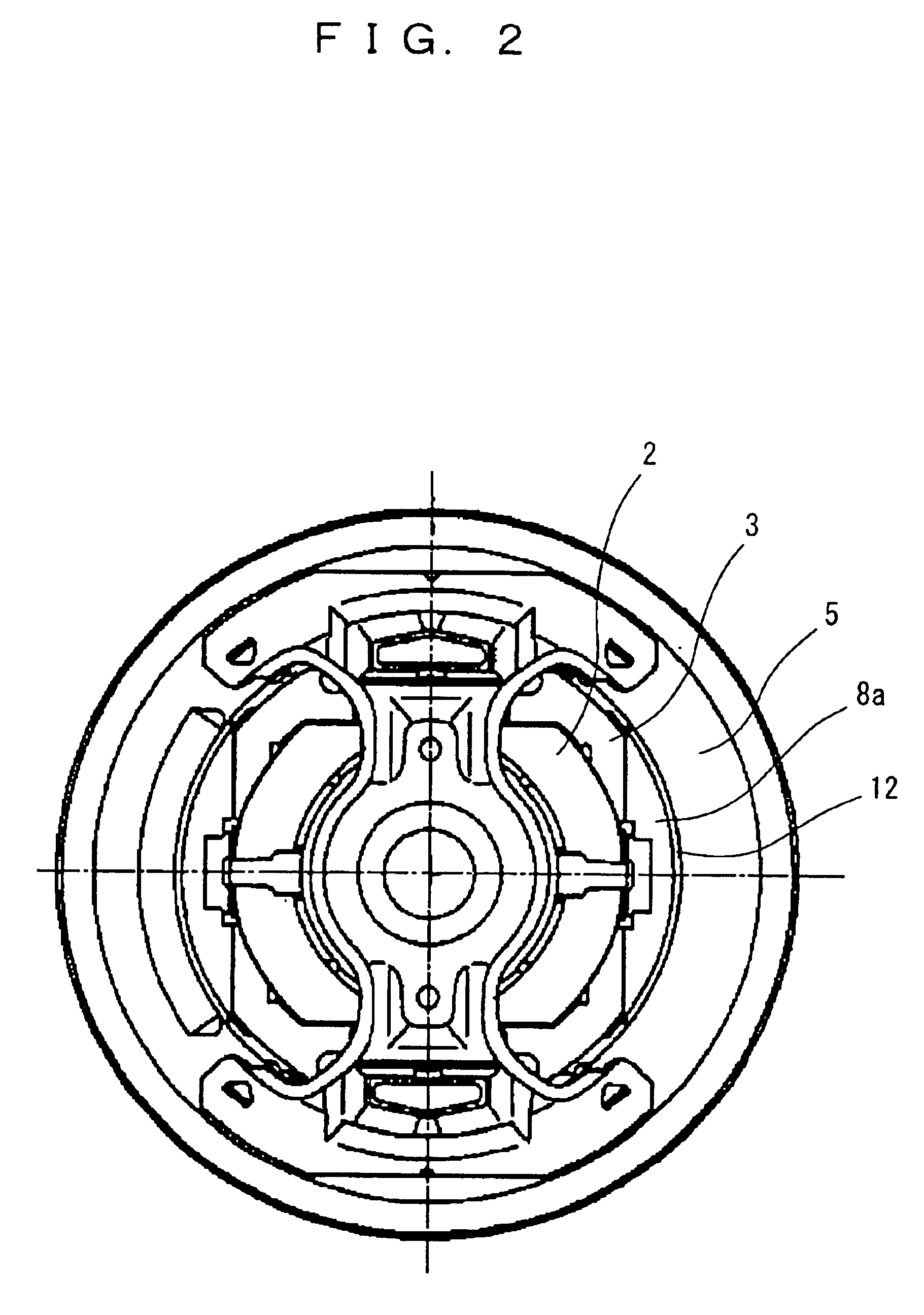
FIG. 1 shows a half cross-sectional view of an electric blower according to one embodiment of the present invention. In FIG. 1, reference numeral 1 denotes a field core, reference numeral 2 denotes a field wiring, reference numeral 3 denotes a spool, reference numeral 4 denotes an armature, reference numeral 5 denotes a motor frame, reference numeral 6 denotes a rotary fan, reference numerals 8a and 8b denote wall surfaces of the spool.
Here, a flow of air which flows into the motor will be explained. The air discharged from the rotary fan 6 flows inside the motor along the motor frame 5, and is separated into a first flow (thick arrow) which is guided to the field winding 2 by the wall surface 8b of the spool 3 at the opposite side of the fan after flowing along the motor frame from a gap 12 between the wall surface 8a of the spool 3 disposed at the end surface of the field core 1 and the motor frame 5, a second flow (thin arrow) which is guided by the wall surface 8a ...
embodiment 2
(Embodiment 2)
FIG. 4 is a half cross-sectional view of the electric blower according to a second embodiment of the present invention. A plurality of raised columns 9 extending inward from the inner diameter of the field core 1 are included at the spool 3 provided at the end surface of the field core 1 at the opposite side from the fan, and the innermost diameter of an exposed portion of the field wiring 2 exposed between the raised columns 9 is made smaller than the inner diameter of the field core 1.
FIG. 5 is a view showing a spool of an electric blower according to a second embodiment of the present invention. The spool 3 includes a terminal stand for holding a tip end of the field wiring 2 wound across the field core 1 and the spool 3 and a connection terminal, and two raised columns 9 for holding and fixing the coil end of the wiring are provided and connected to each other at the center.
embodiment 3
(Embodiment 3)
FIG. 6 shows an electric cleaner loaded with the electric blower at a body 54. The electric cleaner sucks air including dust from a suction port via a hose 52, and the suction force is obtained by rotating a centrifugal fan 6 mounted to an output shaft of the electric blower. The electric blower with excellent wiring cooling ability and high blowing efficiency is used to obtain a large suction force with a small size and light weight.
PUM
 Abstract
Description
Claims
Application Information
 - R&D Engineer
- R&D Manager
- IP Professional
- Industry Leading Data Capabilities
- Powerful AI technology
- Patent DNA Extraction
Browse by: Latest US Patents, China's latest patents, Technical Efficacy Thesaurus, Application Domain, Technology Topic, Popular Technical Reports.
© 2024 PatSnap. All rights reserved.Legal|Privacy policy|Modern Slavery Act Transparency Statement|Sitemap|About US| Contact US: help@patsnap.com


