
Apparatus for attracting mosquitoes and not attracting beneficial insects to electronic bug killers

a technology for electronic bug killers and mosquitoes, applied in electrical devices, insect catchers and killers, ohmic resistance heating, etc., can solve the problems of not particularly well attracting mosquitoes and other biting insects, unnecessary and unwanted killing of these insects, etc., and achieves the effect of reducing the killing of beneficial insects and more effective killing of biting insects

Inactive Publication Date: 2005-03-01
UNIVERSITY OF DELAWARE
View PDF12 Cites 14 Cited by
  • Summary
  • Abstract
  • Description
  • Claims
  • Application Information

AI Technical Summary

Benefits of technology

A primary object of the present invention is to provide a device that produces more effective killing of biting insects, particularly mosquitoes, by commercial electronic insect killers. Another object of the invention is to provide a device for killing mosquitoes and biting insects while reducing the killing of beneficial insects. Another object of the invention is to achieve the aforementioned objects in a cost-effective manner.

Problems solved by technology

Although the references described above disclose devices and methods for attracting and killing insects, none of the aforementioned references fully address the shortcomings of commercial bug zappers.
One problem with these devices is that the light attracts beneficial insects, resulting in unnecessary and unwanted killing of these insects, which may include insects that feed on mosquitoes.
Another problem with bug zappers is that they do not attract mosquitoes and other biting insects particularly well due to the fact that bug zappers rely on light to lure insects into the killing mechanism of the bug zapper.

Method used


Image

  • Apparatus for attracting mosquitoes and not attracting beneficial insects to electronic bug killers
  • Apparatus for attracting mosquitoes and not attracting beneficial insects to electronic bug killers
  • Apparatus for attracting mosquitoes and not attracting beneficial insects to electronic bug killers

Examples


Embodiment Construction

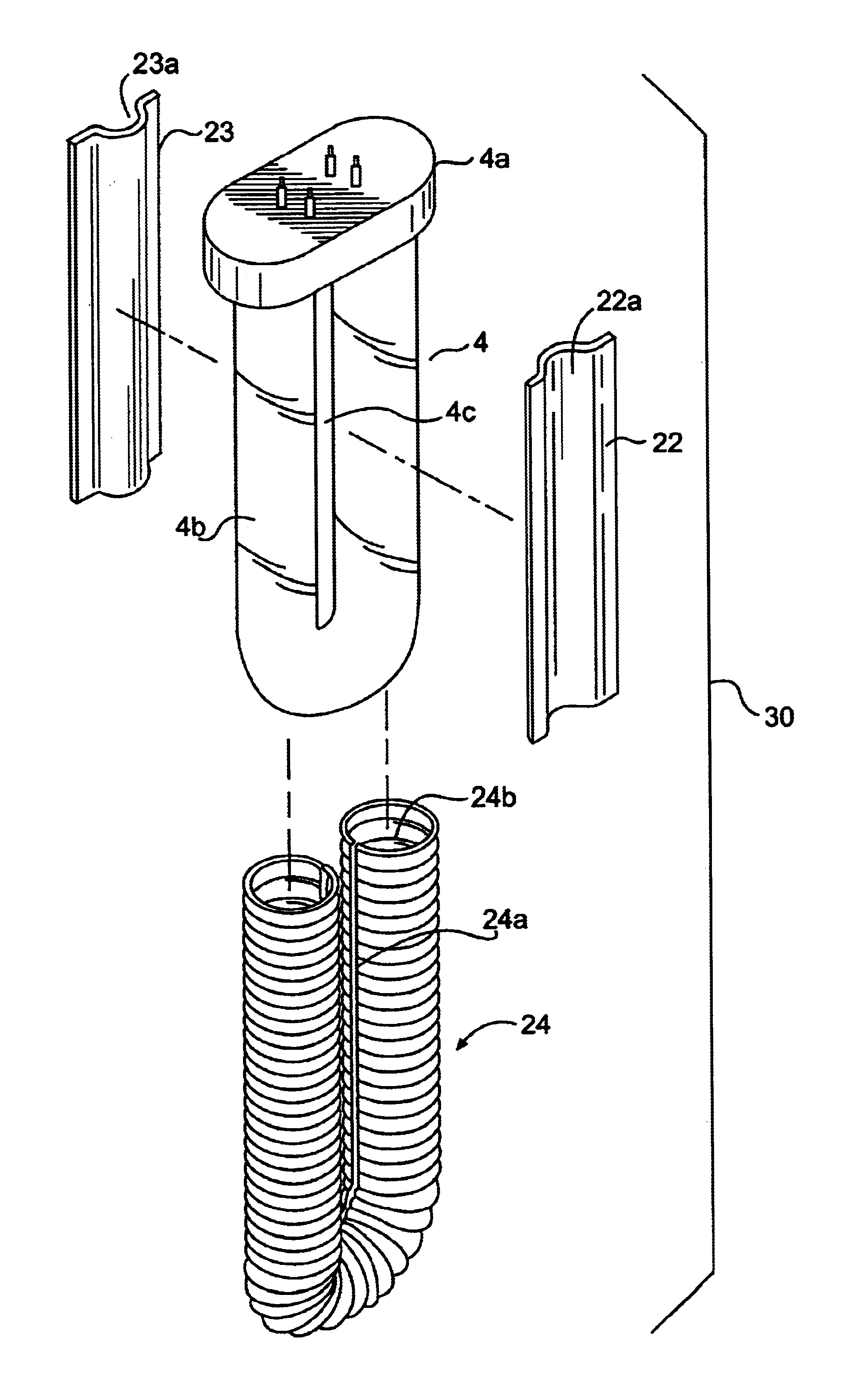
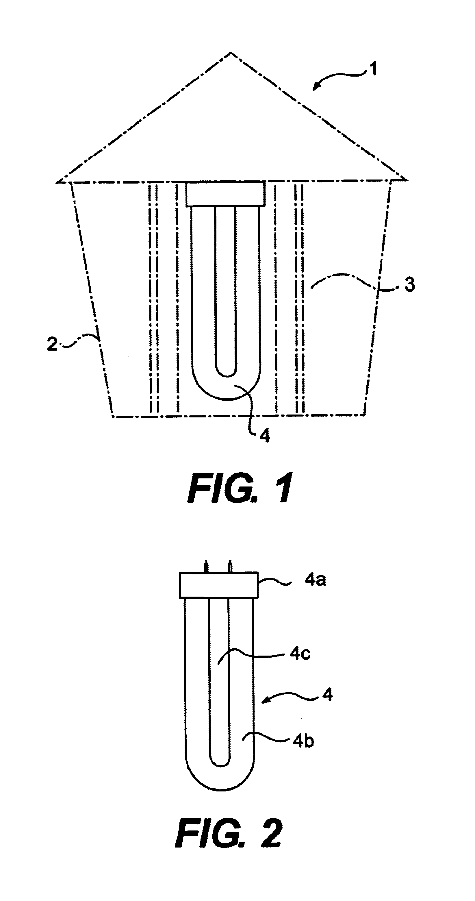
FIG. 1 shows a known commercial electronic insect killing machine, or “bug zapper”1. The bug zapper 1 includes housing 2. A killing mechanism 3, such as an electrostatic grid, is positioned within the housing 2 for electrocuting insects. The killing mechanism 3 is connected to a source of electric potential (not shown). At least one fluorescent or ultraviolet light bulb 4 is positioned within the killing mechanism 3 for attracting insects to the killing mechanism. As best illustrated in FIG. 2, the light bulb 4 is generally U-shaped and includes an insulator end 4a and U-shaped illuminating tube 4b having spaced apart longitudinal light sections. In operation, the light bulb 4 illuminates and thereby attracts insects to the killing mechanism 3, where the insects are electrocuted. The bug zapper 1 is not optimized for killing mosquitoes and other biting insects, as the light bulb 4 tends to attract beneficial insects and not mosquitoes and biting insects, which are attracted to heat ...


PUM


Abstract

An apparatus for attracting mosquitoes to an electronic insect killing machine (i.e., bug zapper) is provided. The apparatus includes a converter device that fits over a fluorescent or ultraviolet light bulb of the bug zapper. The converter device controls radiant light and heat emitted by the light bulb to produce a desired level of heat to create a warm mass, or host simulator that simulates a blood host meal for biting insects. Mosquitoes and other biting insects, which have infrared vision, are attracted to the host simulator. When used with a scented lure that lures the mosquitoes and biting insects near the insect killer, the host simulator lures the mosquitoes and other insects to the killing device of the insect killer. The mosquitoes and biting insects are destroyed once lured to the killing device. The converter device also blocks most of the visible light emitted by the light bulb, and therefore does not lure beneficial insects, which are attracted to visible light, into the insect killer.

Description

The invention relates to improvements in the control of biting insects and the reduction in deaths of beneficial insects by overcoming shortcomings in the use of commercially popular electronic insect killers (bug zappers). The invention particularly relates to controlling mosquitoes in an urban environment.BACKGROUND OF THE INVENTIONDevices for attracting and destroying insects are well known in the art. For example, U.S. Pat. No. 4,908,979 to Hostetter discloses a device that uses a sex attractant, a third generation pesticide, and a black light attached to streetlights to primarily to attract Gypsy Moths. U.S. Pat. No. 4,519,776 to DeYoreo et. al., U.S. Pat. No. 4,907,366 to Balfour, U.S. Pat. Nos. 5,657,576 and 6,088,949 to Nicosia, U.S. Pat. Nos. 5,799,436 and 6,055,766 to Nolan et al., U.S. Pat. No. 6,050,025 to Wilbanks and U.S. Pat. No. 6,305,122 to Iwao all disclose devices that use a scent attractant and a form of heat to lure mosquitoes. U.S. Pat. No. 5,255,468 to Sheshir...

Claims


Application Information

Patent Timeline
IPC IPC(8): A01M1/02A01M1/08A01M1/04
CPCA01M1/04A01M1/08A01M2200/012
Inventor NOSSE, JOHN G.KOCSIS, TERRILL G.
Owner UNIVERSITY OF DELAWARE
Learn More