Method for clock control of clocked half-rail differential logic with sense amplifier and single-rail logic
a technology of differential logic and sense amplifier, applied in the field of logic circuits, can solve the problems of increasing design complexity, increasing power usage, and increasing space use, and achieve the effects of less power, less space, and less hea
- Summary
- Abstract
- Description
- Claims
- Application Information
AI Technical Summary
Benefits of technology
Problems solved by technology
Method used
Image

Examples
Embodiment Construction
The invention will now be described in reference to the accompanying drawings. The same reference numbers may be used throughout the drawings and the following description to refer to the same or like parts.
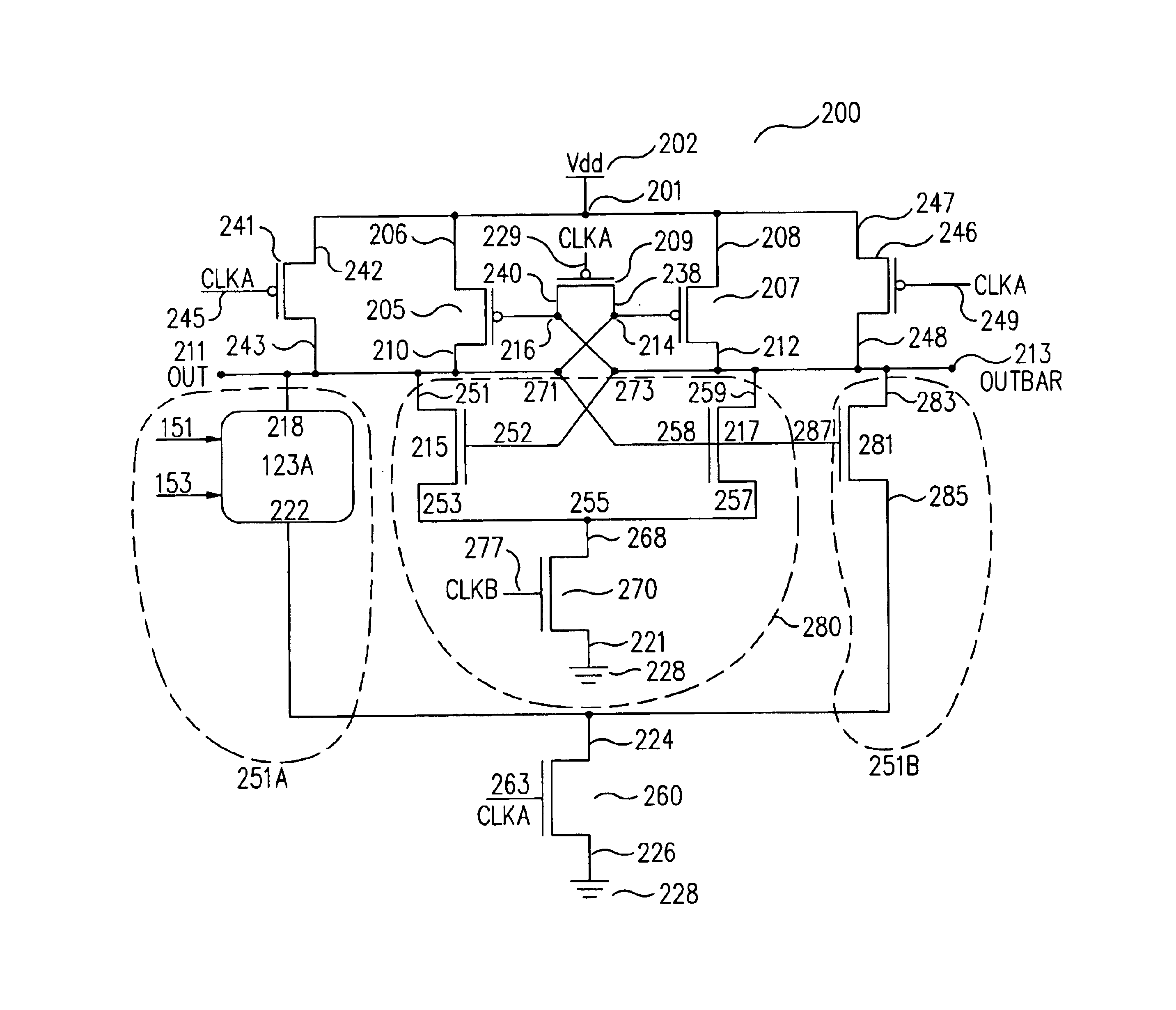
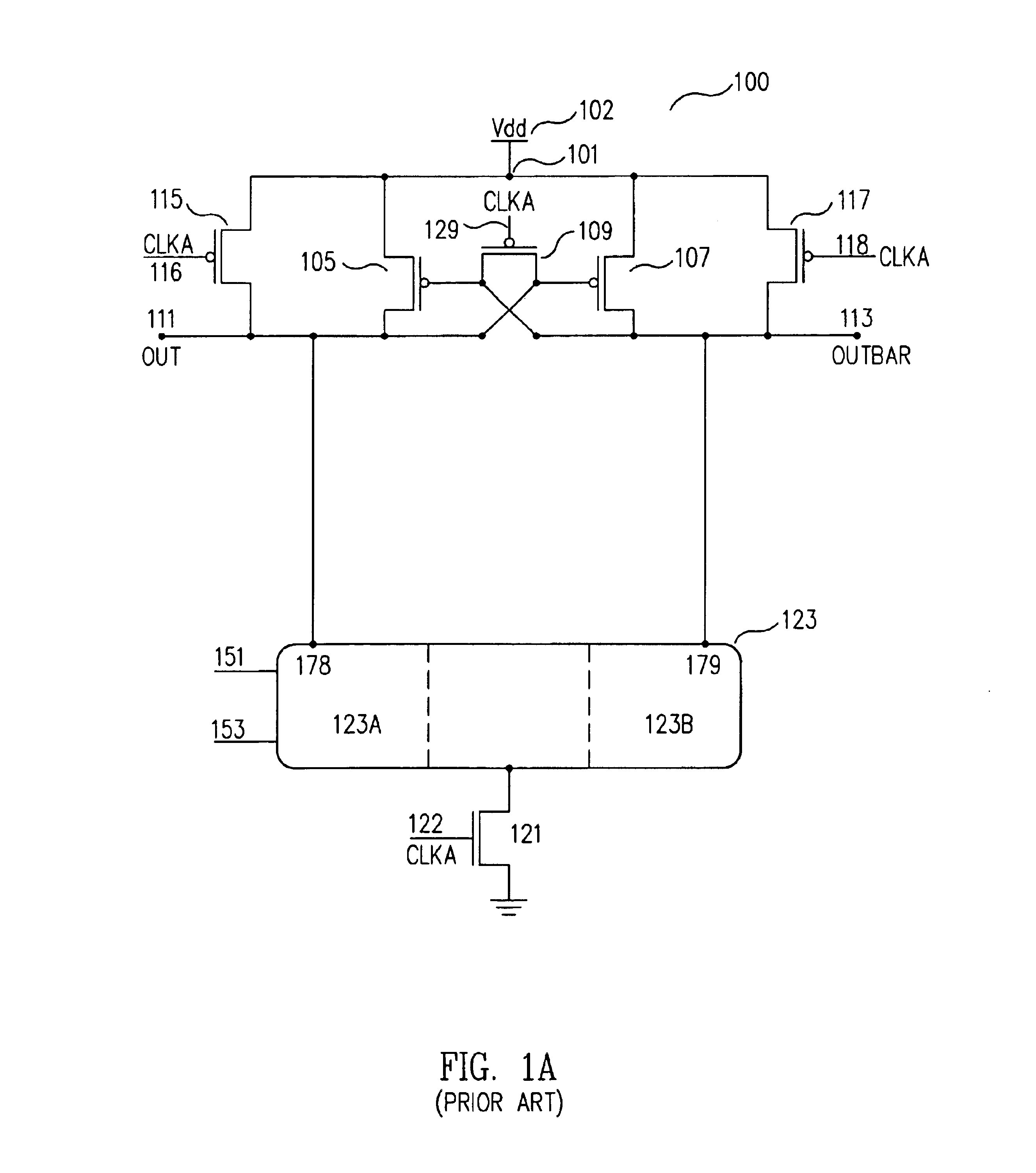
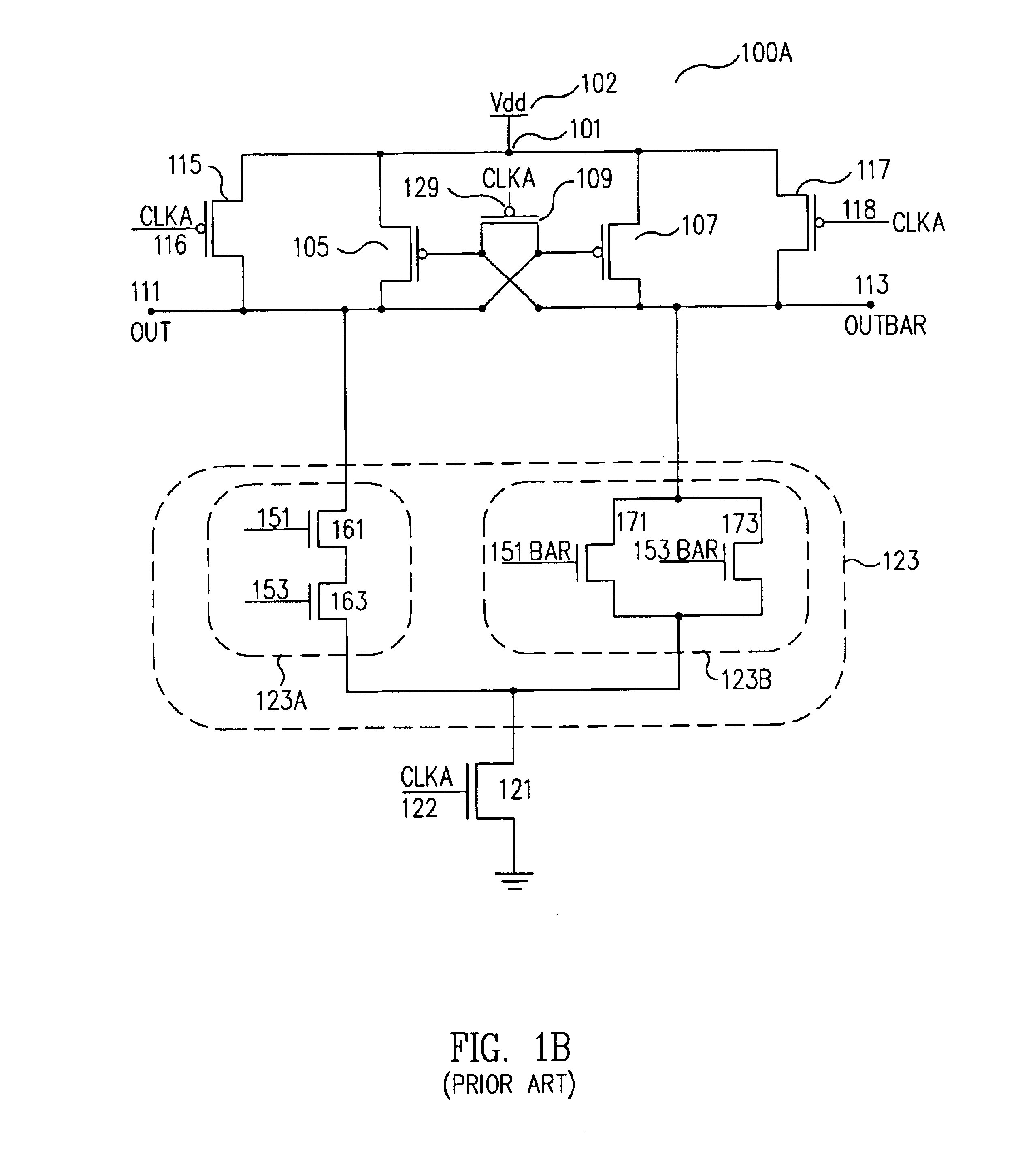
According to the invention, the clocked half-rail differential logic circuits with single-rail logic and sense amplifier (200A in FIG. 2A, 200B in FIG. 2B and 300A, 300B and 300C in FIG. 3) of the invention do not include complementary logic portions (123B in FIGS. 1A and 1B). According to the invention, the complementary logic function of the prior art is replaced by a single complementary output transistor (281 in FIGS. 2A and 2B) appropriately sized to provide the complementary output OUTBAR (213 in FIGS. 2A and 2B). Consequently, clocked half-rail differential logic circuits with single-rail logic and sense amplifier of the invention use less power and, therefore, generate less heat, require less space, and are simpler in design so that they are more flexible, more space effi...
PUM
 Abstract
Description
Claims
Application Information
 - R&D
- Intellectual Property
- Life Sciences
- Materials
- Tech Scout
- Unparalleled Data Quality
- Higher Quality Content
- 60% Fewer Hallucinations
Browse by: Latest US Patents, China's latest patents, Technical Efficacy Thesaurus, Application Domain, Technology Topic, Popular Technical Reports.
© 2025 PatSnap. All rights reserved.Legal|Privacy policy|Modern Slavery Act Transparency Statement|Sitemap|About US| Contact US: help@patsnap.com