Gap seal for sealing a gap between two adjacent components
a gap sealing and adjacent component technology, applied in the direction of engine sealing, leakage prevention, machines/engines, etc., can solve the problem of difficult reliability of the gap sealing
- Summary
- Abstract
- Description
- Claims
- Application Information
AI Technical Summary
Benefits of technology
Problems solved by technology
Method used
Image

Examples
Embodiment Construction
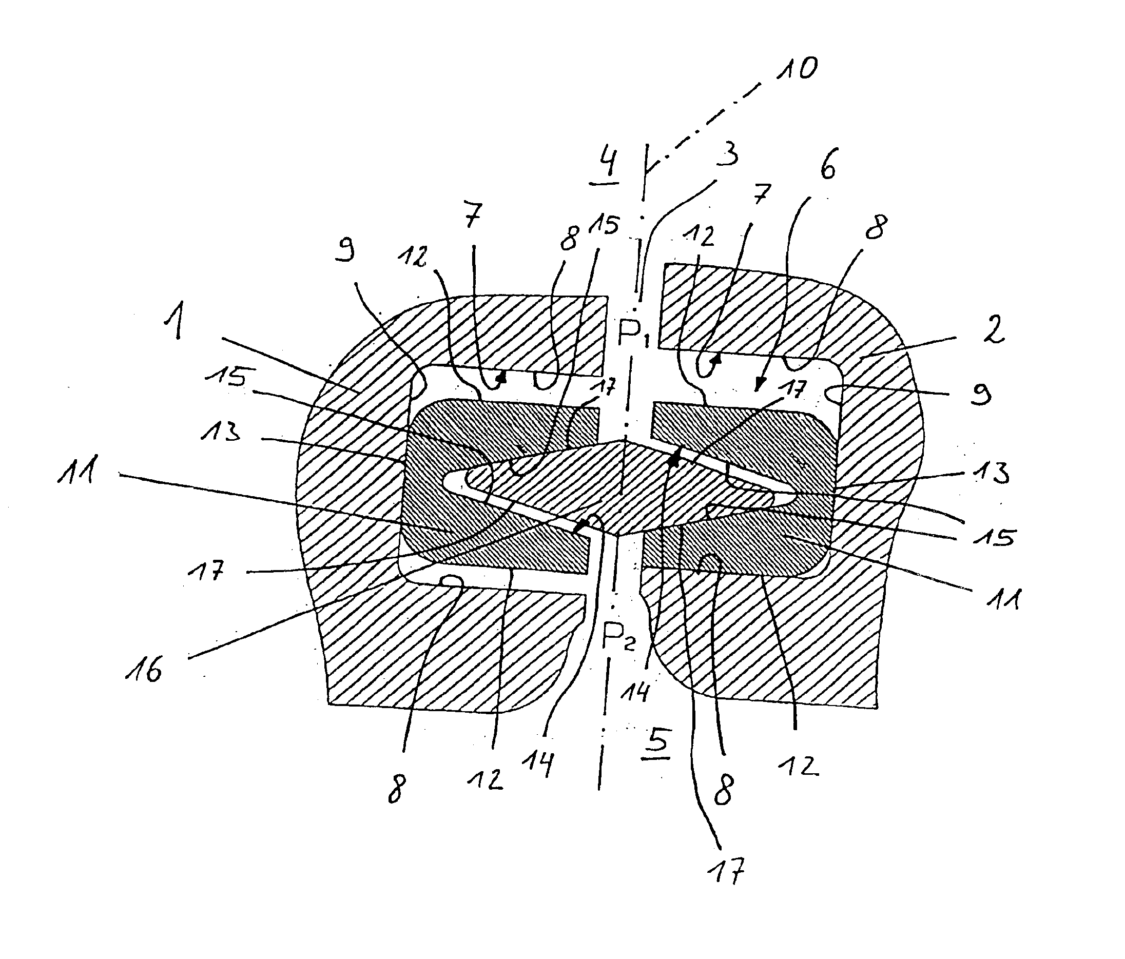
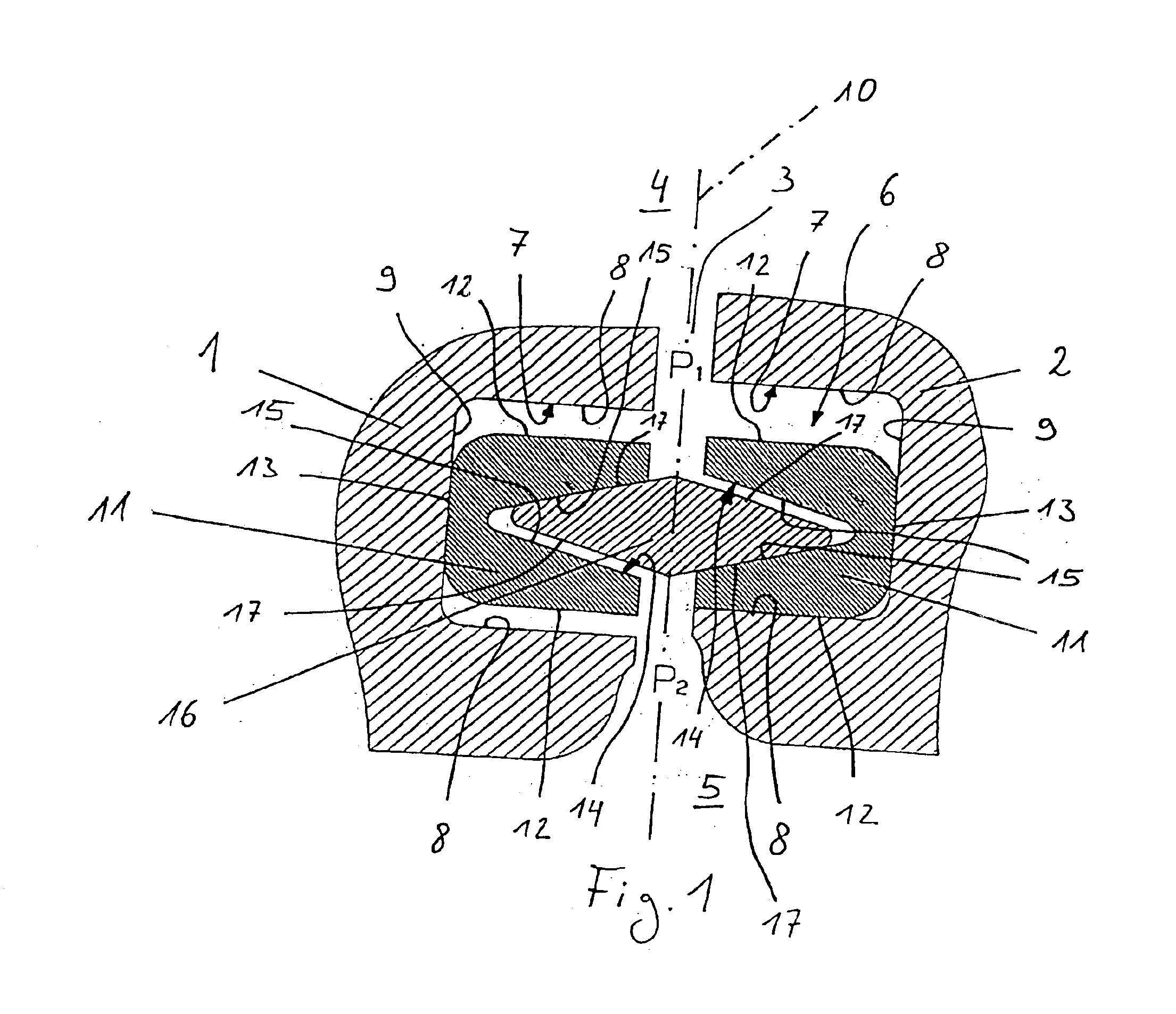
The invention means to remedy this. The invention, as characterized in the claims, has the objective of disclosing an embodiment for a gap of the initially mentioned type, which also ensures a reliable seal of the gap when the components between which the gap is formed are able to move relative to each other.
According to the invention, this objective is realized with a gap seal having the characteristics of claim 1. The secondary claims have advantageous embodiments as their subject.
The invention is based on the general thought of constructing two facing grooves in the gap in the components, into which grooves one each compensation body is set in a movable manner, whereby each compensation body has a V-shaped receiving groove that is open towards the other compensation body, into which receiving groove a mutual, complementarily shaped sealing body with a diamond-or rhombus-shaped cross-section is set in a movable manner. This design has the result that on the one hand relative movem...
PUM
 Abstract
Description
Claims
Application Information
 - R&D
- Intellectual Property
- Life Sciences
- Materials
- Tech Scout
- Unparalleled Data Quality
- Higher Quality Content
- 60% Fewer Hallucinations
Browse by: Latest US Patents, China's latest patents, Technical Efficacy Thesaurus, Application Domain, Technology Topic, Popular Technical Reports.
© 2025 PatSnap. All rights reserved.Legal|Privacy policy|Modern Slavery Act Transparency Statement|Sitemap|About US| Contact US: help@patsnap.com