
Safety guard for band saws

a safety guard and band saw technology, applied in band saws, strap saws, manufacturing tools, etc., can solve the problems of unadjustable protection of conventional band saw blade guards, possible hazardous conditions, and accidents that affect the safety of workers or operators, and achieve the effect of preventing accidental injuries

Inactive Publication Date: 2005-02-22
BENEDICT CHARLES E
View PDF21 Cites 11 Cited by
  • Summary
  • Abstract
  • Description
  • Claims
  • Application Information

AI Technical Summary

Benefits of technology

A locking mechanism is provided for normally securing the guard in the first position to thereby prevent accidental displacement of the guard. The locking mechanism is designed to be manually released to permit movement from the first position, such that a workpiece may pass beneath the guard when the saw is in use.
It is also an object of the present invention to provide a safety device for band saws which may be retrofitted to conventional band saws in an inexpensive manner such that conventional band saws may be made safer for operators.

Problems solved by technology

Unfortunately, conventional band saws have a significant portion of the saw blade exposed between the housing and the band saw table in order to provide space to maneuver a workpiece relative to the blade when the workpiece is supported on a support surface of the table.
Because of this exposed length of cutting blade, numerous accidents have occurred by workers or operators accidently contacting the blade.
However, conventional band saw blade guards do not provide adequate protection to prevent accidental contact with the saw blade under many circumstances.
Often, conventional guards can be inadvertently moved from a covering relationship with respect to the saw blade thereby creating a possibly hazardous condition wherein an operator can accidently make contact with the unprotected blade.
The reliance on manual return of a guard to a safety position creates a further potentially hazardous condition.
In addition to the foregoing, many guards which have been designed for use with band saws only provide a structure which shields a portion of the length of the band saw blade and do not provide any safety structure for preventing accidental contact of a worker's hands with the saw blade when a workpiece is being maneuvered relative to the saw blade.

Method used


Image

  • Safety guard for band saws
  • Safety guard for band saws
  • Safety guard for band saws

Examples


Embodiment Construction

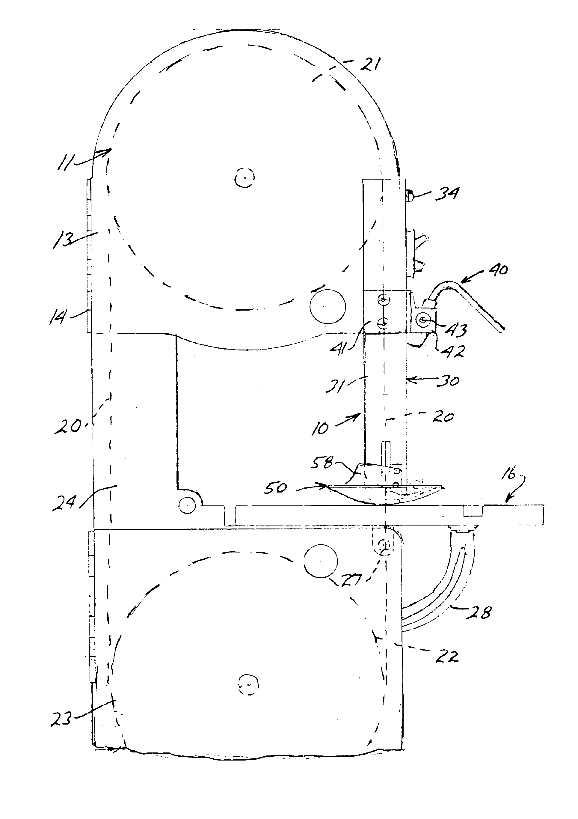
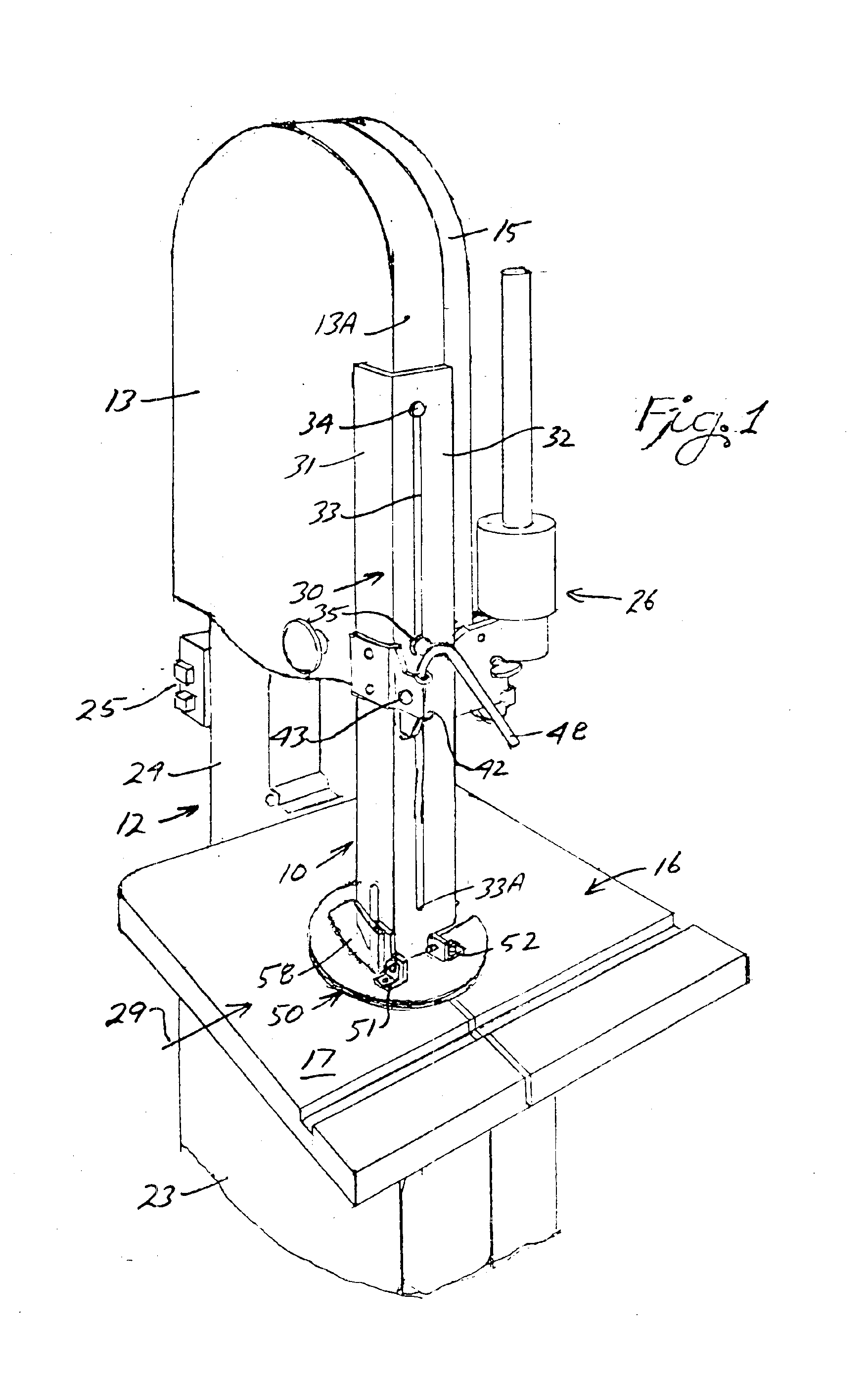
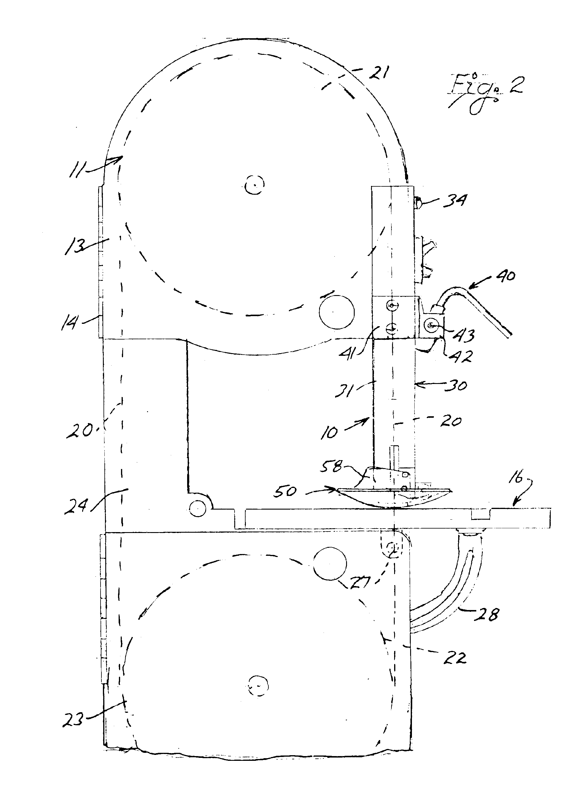
With continued reference to the drawing figures, the safety device 10 of the present invention is shown as being mounted to an upper housing 11 of a conventional powered band saw 12. The housing includes a door 13 which is pivotally mounted at 14 to a fixed housing cover 15. The housing 11 is vertically spaced relative to a table 16 having a workpiece support surface 17 along which workpieces “W” are guided relative to a continuous band saw blade 20, as is illustrated in FIG. 8.

The continuous band saw blade 20 is mounted about an upper guide wheel sprocket or roller 21 mounted within the housing 11 and a lower guide wheel, sprocket or roller 22 which is mounted within a lower housing 23 of the band saw. A motor, not shown, is mounted within the lower housing 23 so as to drive the wheel, sprocket or drive roller 22 to move the saw blade relative to the work support table 16. A rear run 20′ of the saw blade extends within an enclosed support column 24 which supports the upper housing ...


PUM

PropertyMeasurementUnit
Transparencyaaaaaaaaaa

Abstract

The safety device for a band saw which includes a vertically displaceable guard which is slidably mounted to a housing of the saw and having a lower end adjacent the table of saw and wherein a pivotable shield is carried by the lower end of the guard. A locking mechanism normally secures the guard in a lowered covering relationship to a band saw blade and must be manually released to permit raising of the guard to allow a workpiece to be moved beneath the shield to be cut by the band saw blade.

Description

BACKGROUND OF THE INVENTIONField of the InventionThis invention is generally directed to safety guards or shields used with power cutting tools and, more particularly, to a guard for covering an exposed portion of a band saw blade which normally extends between a housing of the band saw and a work table through which the band saw blade passes and which table is in spaced relationship below to the housing. The guard is specifically designed to be retained in a covering relationship with respect to the normally exposed portion of the band saw blade unless manually released and thereafter, once a workpiece is cut, the guard automatically locks in a lowered covering relationship with respect to the saw blade to thereby prevent accidental contact with the saw blade by an operator.The guard also supports a shield which extends radially outwardly from a lower portion thereof through which the band saw blade passes. The shield prevents accidental contact with the blade when the guard is rai...

Claims


Application Information

Patent Timeline
IPC IPC(8): B27G19/00B27G19/06
CPCB27G19/06Y10S83/01Y10T83/7264Y10T83/96Y10T83/8723
Inventor BENEDICT, CHARLES E.CORBETT, STEPHEN R.YATES, CHRISTIAN TALLAHASSEEBOOESHAGHI, FARHAD
Owner BENEDICT CHARLES E
Learn More