
Phase-change optical recording media

a recording media and phase change technology, applied in photomechanical equipment, instruments, nuclear engineering, etc., can solve the problems of unerased signals, uncompletely erased initial signals, worsened erasability, etc., to improve erasability in overwriting, improve recording sensitivity, and high linear velocity

Inactive Publication Date: 2005-02-15
TOSOH CORP
View PDF8 Cites 3 Cited by
  • Summary
  • Abstract
  • Description
  • Claims
  • Application Information

AI Technical Summary

Benefits of technology

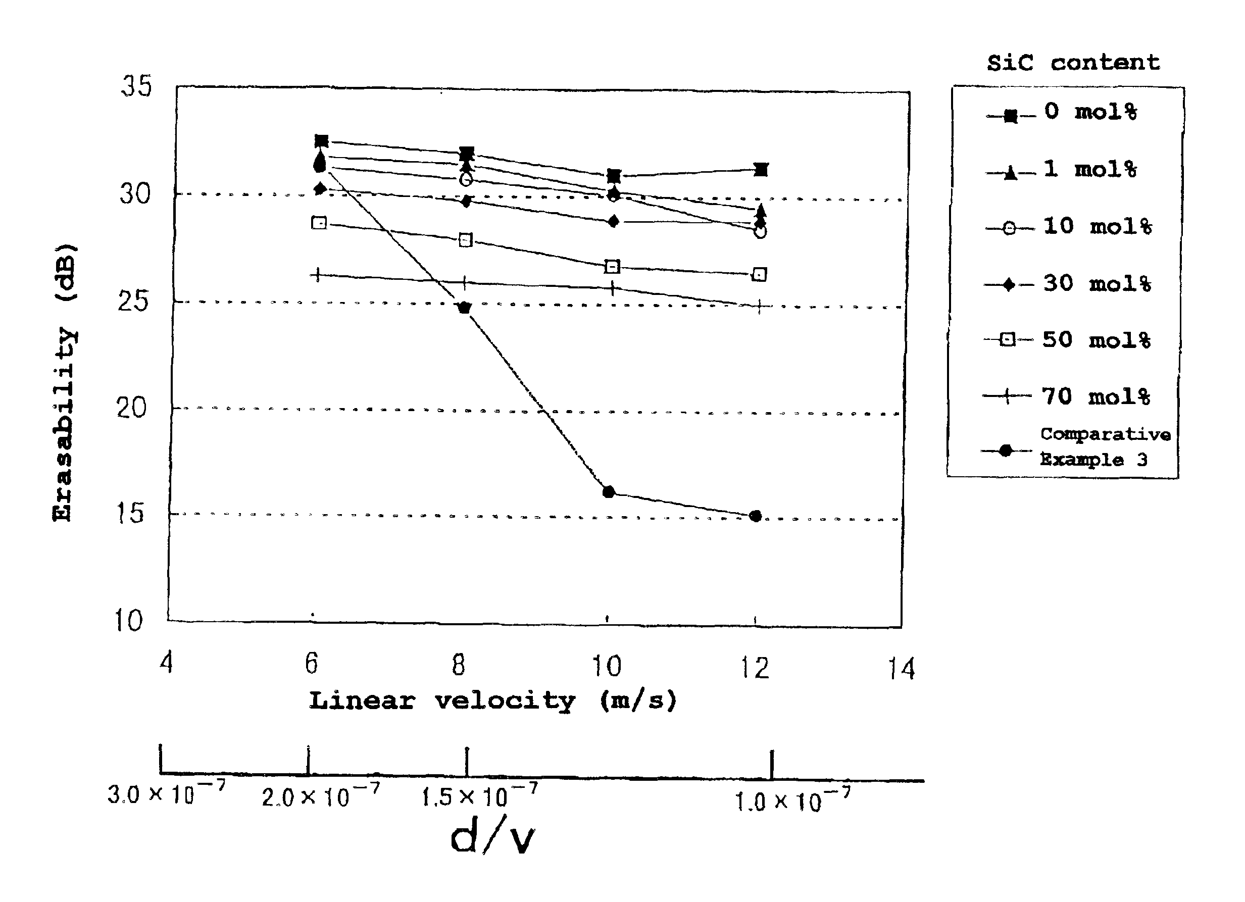
[0006]An object of the invention is to provide phase-change optical recording media which are effective in attaining diminution in unerased signals and an improvement in the erasability in overwriting at a high linear velocity and have high recording sensitivity, satisfactory OW cycling durability, and satisfactory weatherability.
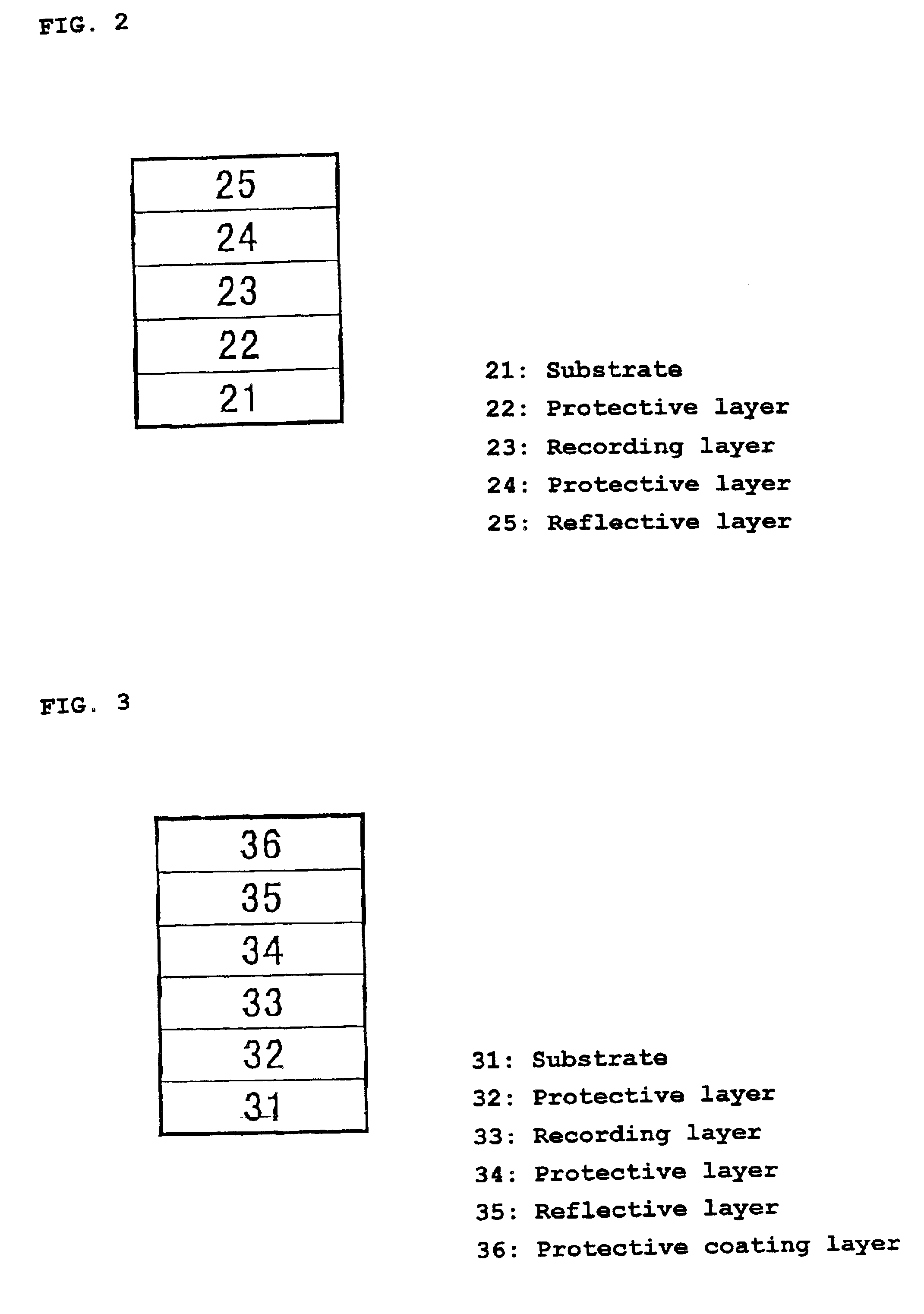
[0007]The present inventors made intensive investigations under the circumstances described above. As a result, they have found that in a phase-change optical recording medium which comprises a substrate and formed thereon a multilayered film comprising a protective layer and a recording layer and in which information is recorded / erased based on reversible phase changes in the recording layer between a crystalline phase and an amorphous phase, the erasability and durability in overwriting at a high linear velocity can be improved by forming the protective layer so as to comprise specific components. They have further found that this effect is enhanced by regulating the proportion of a component in the protective layer so as to be in a specific range. The invention has been completed based on these findings.

Problems solved by technology

However, these recording media have a drawback that when a high linear velocity is used so as to realize a higher transfer rate, the initial signals are not completely erased through overwriting (OW) and unerased signals remain.
Namely, an increase in linear velocity results in a worsened erasability.

Method used


Image

  • Phase-change optical recording media
  • Phase-change optical recording media
  • Phase-change optical recording media

Examples


example 3

[0045]Phase-change optical recording media were produced in the same manner as in Example 1, except that the first protective layer and second protective layer were formed so as to contain 10 mol % TiC (Example 3, Sample 1), 10 mol % TaC (Example 3, Sample 2), or 10 mol % Nb2C (Example 3, Sample 3) in place of the SiC.

example 4

[0046]Phase-change optical recording media were produced (Example 4, Samples 1 to 3) in the same manner as in Example 3, except that Al2O3 was used in place of the Ta2O5 in the first protective layer and second protective layer.

example 5

[0047]A phase-change optical recording medium was produced in the same manner as in Example 1, except that a film consisting of Ta2O5 and 10 mol % SiC was formed as the first protective layer and a film comprising ZnS and 20 mol % SiO2 was formed as the second protective layer.


PUM

PropertyMeasurementUnit
thicknessaaaaaaaaaa
thicknessaaaaaaaaaa
thicknessaaaaaaaaaa

Abstract

A phase-change optical recording medium which attains a high erasability in overwriting at a high linear velocity and has high recording sensitivity, excellent OW cycling characteristics, and excellent weatherability. The phase-change optical recording medium comprises a substrate and formed thereon a multilayered film comprising a protective layer and a recording layer and is that information is recorded / erased based on reversible phase changes in the recording layer between a crystalline phase and an amorphous phase, wherein the protective layer is a film made of an oxide of tantalum or aluminum and at least one carbide, and the content of the carbide is from 1 to 40 mol %.

Description

FIELD OF THE INVENTION[0002]The present invention relates to rewritable optical information recording media. More particularly, the invention relates to phase-change optical recording media in which information is recorded, reproduced, and erased based on phase changes in the recording layer which are caused by a laser beam or the like.DESCRIPTION OF THE RELATED ART[0003]Phase-change optical recording disks are a kind of rewritable optical recording disk, and information is recorded therein based on reversible phase changes (mostly between crystalline phase and amorphous phase) in the recording layer. In the phase-change optical recording disks, in general, light intensity modulation overwriting in the single recording layer is possible with a single head and signals are read out based on a change in reflectance accompanying a phase change. A feature of these recording media hence resides in that they are highly interchangeable with existing optical recording disks including CD-ROMs...

Claims


Application Information

Patent Timeline
Patent Type & Authority Patents(United States)
IPC IPC(8): C23C14/06G11B7/243G11B7/257
CPCC23C14/06G11B7/2578Y10S430/146G11B7/2533G11B7/2534G11B7/2542G11B7/2585G11B2007/24308G11B2007/2431G11B2007/24312G11B2007/24314G11B2007/24316G11B2007/25706G11B2007/25708G11B2007/2571G11B2007/25711G11B2007/25715G11B2007/25716G11B7/2531
Inventor INASE, TOSHIOIIGUSA, HITOSHI
Owner TOSOH CORP
Learn More