Eureka AIR delivers breakthrough ideas for toughest innovation challenges, trusted by R&D personnel around the world.

Filter system employing microwave regeneration

a filter system and microwave technology, applied in the field of filter systems, can solve the problems of excessive pressure drop across the filter, undesirable or even disastrous, etc., and achieve the effect of avoiding undesired pressure drop (back pressure) and large gas flow

Inactive Publication Date: 2005-02-15
INDAL CERAMIC SOLUTIONS
View PDF22 Cites 12 Cited by
  • Summary
  • Abstract
  • Description
  • Claims
  • Application Information

AI Technical Summary

Benefits of technology

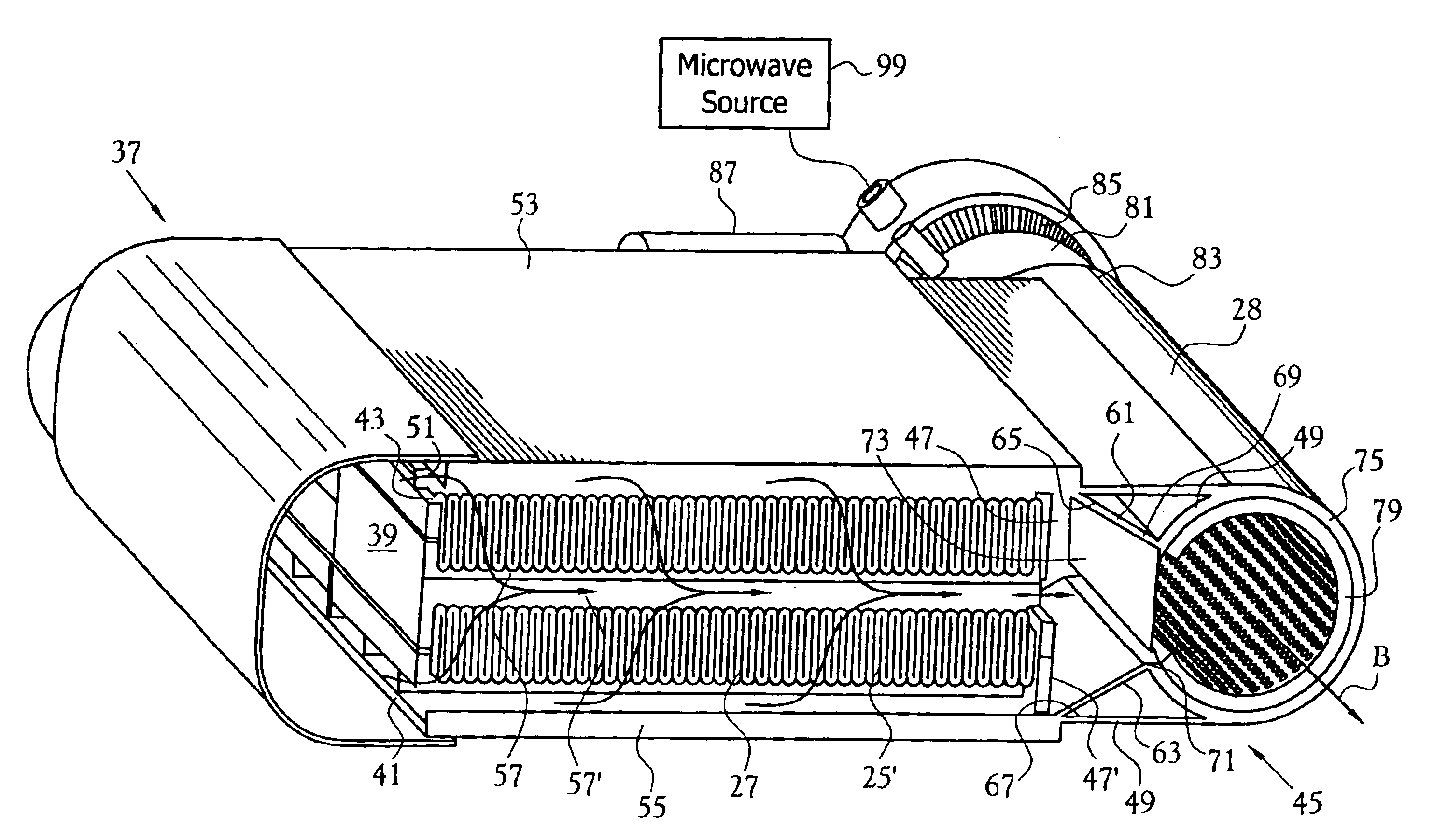
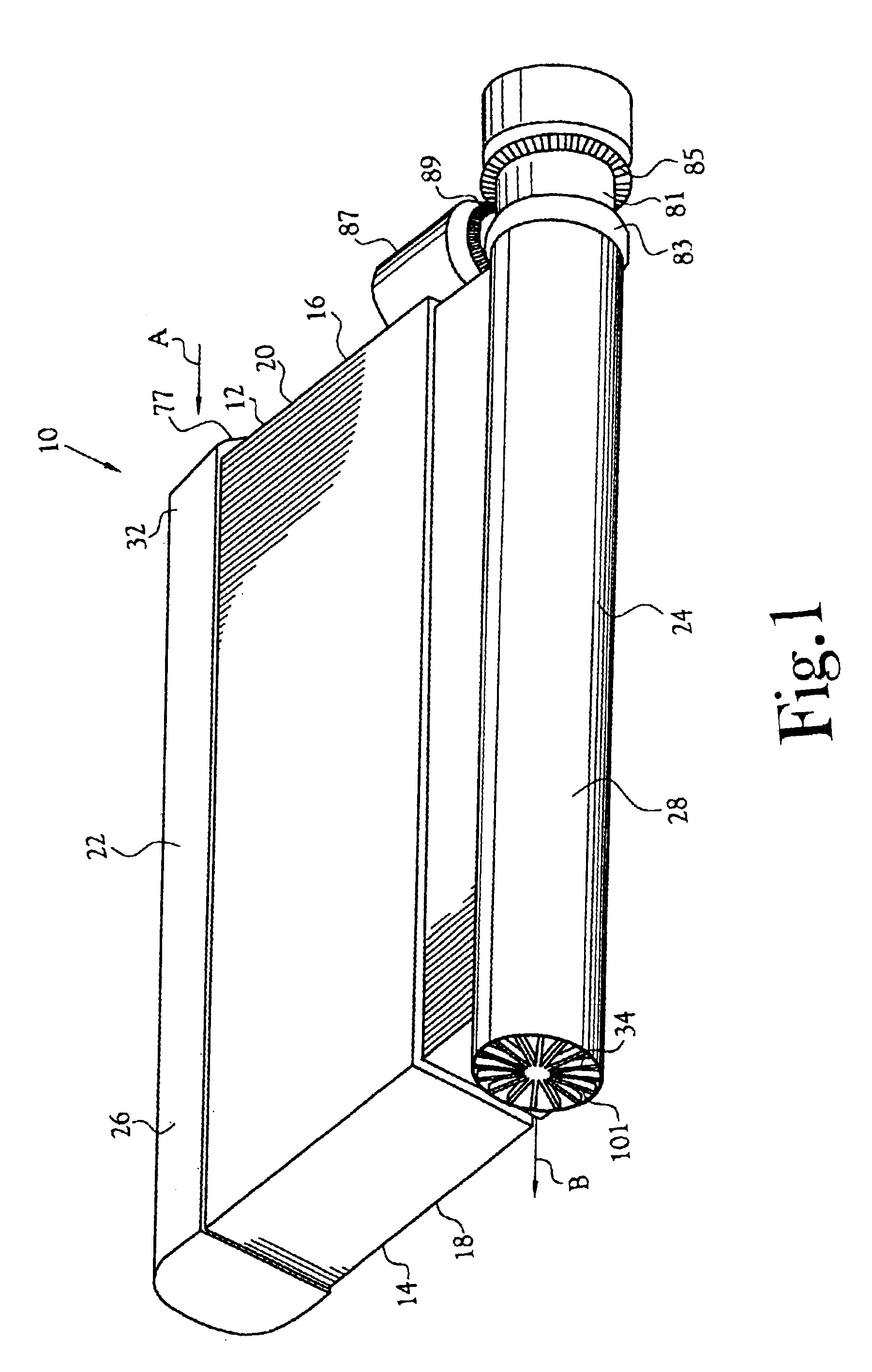
In one embodiment, the overall filter structure comprises at least one, and preferably a plurality of individual housing / pleated filter subassemblies, all aligned in a common plane or parallel planes so that their respective outlet sides are aligned such that they share a common elongated exhaust plenum. Within, and concentrically of, the interior of this exhaust plenum there is provided a rotatable, preferably tubular, member. This member includes a plurality (one for each filter subassembly or grouping of filter subassemblies) of ceramic microwave-permeable segments spaced apart from one another along the length of the wall of the tubular member. The remainder of the tube includes holes of a proper diameter to stop 2.45 GH microwaves while allowing the free passage of exhaust gas therethrough. Thus, each segment is sized and designed to cover a respective one or ones of the outlets of the aligned outlets of the multiple subassemblies to define a transparent window for the admission of microwaves (while preventing the flow of exhaust gas therepast), but stopping exhaust flow, passing along the length of the tubular member, into a respective one or ones of the filter subassemblies when the segment is in register with the outlet from a respective filter subassembly. In this embodiment, each segment also is positioned at a location which is progressively rotated about the outer circumferential wall of the tubular member. In one embodiment, no two filter subassemblies are open to microwaves at any given time. In other embodiments, only a limited number of filter subassemblies are open to microwaves at any given time Thus, through selective rotation of the tubular member about its longitudinal axis, admission of microwaves into a filter subassembly may be restricted to only a single filter subassembly or a selected group of filter subassemblies, at any given time, thereby providing for the regeneration of a single filter subassembly or selected group of filter subassemblies while the remaining filter subassemblies remain available for receiving and filtering of the inlet gas stream flowing through the inlet plenum and exhausting of the cleaned gas stream via the exhaust plenum. This selective regeneration of the filter subassemblies is conducted in situ and provides for sequential regeneration of the multiple subassemblies, thereby preventing any material interruption of the flow of the gas stream through the overall filter system, hence the ability of the overall filter system to accommodate a substantially larger volume of gas flow, and avoiding undesired pressure drop (back pressure) across any one of the multiple filter subassemblies, all without deleterious effects on the normal operation of the generator of the contaminated gas stream, e.g., a diesel engine.

Problems solved by technology

However, these prior art filters and / or the systems within which they are employed suffer from problems of premature clogging of the entry ends of the tubular chambers defined by the corrugations, and from inadequate capacity to accommodate the anticipated or actual overall flow of gas streams through the filter, resulting in excessive pressure drop across the filter, at times creating undesirable or even disastrous results, and / or regeneration only during shut-down or diversion of the source of the gas stream, such diversion effectively taking the filtration system offline.

Method used


Image

  • Filter system employing microwave regeneration
  • Filter system employing microwave regeneration
  • Filter system employing microwave regeneration

Examples


Embodiment Construction

Referring specifically to FIG. 1, the depicted embodiment of a filter system 10 of the present invention includes a housing 12, which in the depicted embodiment is of a generally rectangular cross-section having its opposite short sides 14,16 sealed by respective end plates 18,20. Each of the opposite longer sides 22,24 of the housing preferably is rounded and partially defines an inlet plenum 26 and an outlet plenum 28, respectively, for the flow of a gas stream (see arrows) through the filter system.

Internally of the housing there is provided at least one, and preferably a plurality of filter modules 25 (see FIG. 5), each of which, in the depicted embodiment includes a pleated ceramic filter paper 27 captured between first and second comb elements 29,31 (typical), respectively, (see FIGS. 6 and 7). As seen in FIGS. 2 and 5, the top margins (ribs) 33 of each comb projects above the planar level of the pleated paper, thereby defining multiple gas flow channels 35 (typical, see arrow...


PUM

PropertyMeasurementUnit
temperaturesaaaaaaaaaa
timeaaaaaaaaaa
microwave energyaaaaaaaaaa

Abstract

A filtration system (10) operable at elevated temperatures and regenerateable in situ employing microwave energy (99). In one embodiment, the system includes multiple channels (35) with means for selectively placing individual ones of the channels on-line for filtration and off-line for regeneration.

Description

BACKGROUND OF THE INVENTION1. Field of InventionThis invention relates to filters and filter systems which are operable at elevated temperatures and capable of extracting volatilizable particulates from a gas stream. In particular, this invention relates to ceramic fiber-paper based filters which may be regenerated in situ employing microwave energy.2. Background of the InventionHeretofore, it has been known in the art that ceramic fibers may be formed into a ceramic paper. It is also suggested in the prior art that this paper may be corrugated and wound into a cylindrical filter for the capture of volatilizable particulates from a gas stream, and that the filter may be regenerated employing microwaves.However, these prior art filters and / or the systems within which they are employed suffer from problems of premature clogging of the entry ends of the tubular chambers defined by the corrugations, and from inadequate capacity to accommodate the anticipated or actual overall flow of ga...

Claims


Application Information

Patent Timeline
Patent Type & Authority Patents(United States)
IPC IPC(8): B01D46/24B01D46/52B01D46/00B01D46/10
CPCB01D46/002B01D46/0057B01D46/0058B01D46/521B01D46/523B01D46/10B01D2273/22B01D46/90B01D46/66B01D46/58
Inventor NIXDORF, RICHARD D.
Owner INDAL CERAMIC SOLUTIONS
Why Eureka
Eureka Blog
Learn More