Heat exchange and mass transfer packing and packed column utilizing same

Active Publication Date: 2005-02-15
YURIUSU MONTSU
View PDF10 Cites 2 Cited by
  • Summary
  • Abstract
  • Description
  • Claims
  • Application Information

AI Technical Summary

Benefits of technology

It is, therefore, the principal object of the present invention to provide an improved packing and especially a structured cross flow packing for a heat exchange and/or mass t

Problems solved by technology

However, with that reduction in the wall thickness there has been some reduction in the mechanical stability of the packing and some limitations as to the packing height which can be used since there is a danger of mechanical deformat

Method used


Image

  • Heat exchange and mass transfer packing and packed column utilizing same
  • Heat exchange and mass transfer packing and packed column utilizing same
  • Heat exchange and mass transfer packing and packed column utilizing same

Examples


Example

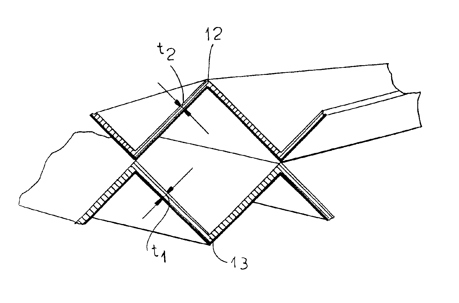
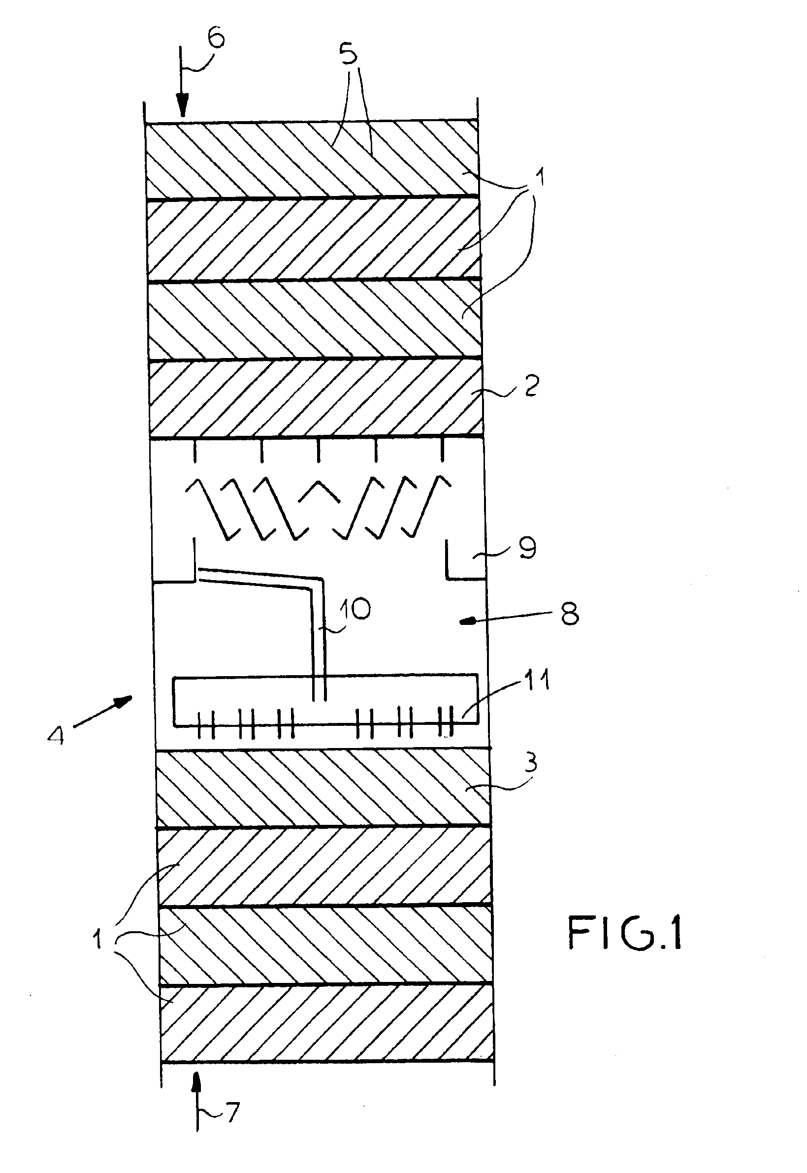
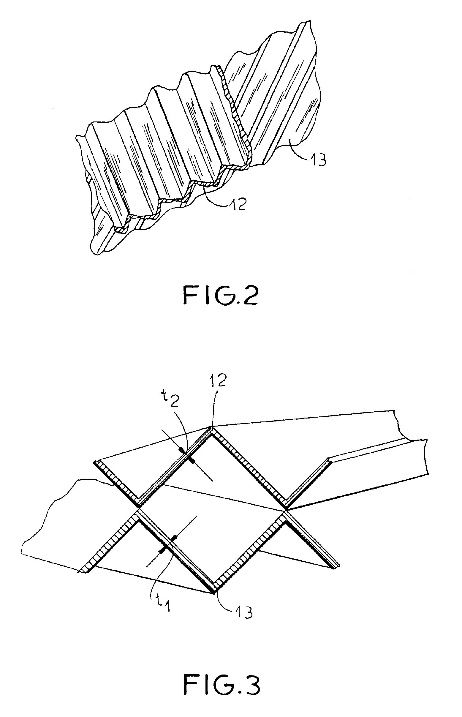
FIG. 1 shows a column for heat exchange or mass transfer between a liquid and a gas which is provided with a plurality of packings 1-3. The liquid is assumed to pass downwardly through the column in the direction represented by the arrow 6 while the gas passes upwardly through the column as represented by the arrow 7. The packing layers 1 and 2 of the upper bed and the packing layers 3 and 1 of the lower bed are all composed of corrugated or folded plates or sheets 5 such that the corrugations, ribs, folds or bends of neighboring sheets or plates cross one another at an angle of 60 to 90° so that plates with corrugations that run generally crosswise to each other or have their corrugations turned at angles of 60 to 90° adjoin one another, preferably in the manner described in DE 100 01 694.

Between these beds, a liquid redistributor stage 8 can be provided which contains a collecting trough 9 collecting the liquid from the periphery of the upper bed and feeding that liquid via a down...


PUM

PropertyMeasurementUnit
Thicknessaaaaaaaaaa
Thicknessaaaaaaaaaa
Thicknessaaaaaaaaaa

Abstract

A heat exchange or mass transfer column in which the packing bed is formed from individual packing layers wherein the sheet metal plates of the packing have different thicknesses.

Description

FIELD OF THE INVENTIONOur present invention relates to a packing for heat exchange and / or mass transfer between liquids and gases in columns in which the packing bed or beds are formed from individual packing layers.BACKGROUND OF THE INVENTIONIn distillations, absorption, gas-scrubbing and like operations, columns are widely used which include baffling structures to promote the heat exchange and mass transfer between a liquid phase and a gas phase. These structures can be trays or the like, for example, bell type or bubble trays, sieve trays and valve trays, or the structures can be randomly arranged packing bodies like, for example, Raschig rings, Pall rings or saddle-shaped bodies, or the structures can be ordered or structured packings like, for example, plates composed of sheet metal with corrugations or folds.The ordered or structured packing can have geometries providing a cross channel structure or cross flow channels. Such structured packings are now widely used. As a genera...

Claims


Application Information

Patent Timeline
IPC IPC(8): B01J19/32
CPCB01J19/32B01J2219/3221B01J2219/32213B01J2219/32227B01J2219/32237Y10S261/72B01J2219/32262B01J2219/32272B01J2219/32408B01J2219/3325B01J2219/32255
Inventor ZICH, EGONJANSEN, HELMUTRIETFORT, THOMASKAIBEL, BJORN
Owner YURIUSU MONTSU
Why Eureka
Try Eureka