Cane handle with adjustable supporting loop

Inactive Publication Date: 2005-02-08
LENHART KLAUS
View PDF19 Cites 25 Cited by
  • Summary
  • Abstract
  • Description
  • Claims
  • Application Information

AI Technical Summary

Benefits of technology

By means of the steps in accordance with the invention it is achieved that the transition from one to the other position (i.e. adjustment or clamping) is exclusively achieved by the pivot position of the clamping element. In turn, this pivot position depends on whether the hand loop is pulled downward, or horizontally, or upward in relation to the cane handle of the cane. In this way the clamping position is always present, or set, in the customary position of use (downward pull on the hand loop), so that in the meantime an unintentional displacement is not possible. An adjustment position, i.e. increasing or decreasing the loop, is possible only if the hand loop is purposely used in the horizontal or obliquely upward pulled position. This has the further advantage that when the cane is caught on an object in an unintended way, the said pull on the hand loop upward in relation to the cane handle results in a change from the clamped position to the adjusting position, so that the hand loop can be extended, which can result in the hand slipping out of the loop, and therefore in a kind of safety release. With this cane handle the separate displacement of the clamping device is not necessary, which results in a simpler manipulation and a reduced outlay for components. Moreover, the loop strip can be produced in a cost-effective manner.
A structurally robust a rapidly and easily mountable construction results when the characteristics in accordance with the present invention are provided.
A sufficient and structurally simple release of the clamping results from the characteristics in accordance with the present invention. A reinforcement of the clamping is achieved when taking the characteristics of the present invention into consideration.

Problems solved by technology

In this way the clamping position is always present, or set, in the customary position of use (downward pull on the hand loop), so that in the meantime an unintentional displacement is not possible.

Method used


Image

  • Cane handle with adjustable supporting loop
  • Cane handle with adjustable supporting loop
  • Cane handle with adjustable supporting loop

Examples


Embodiment Construction

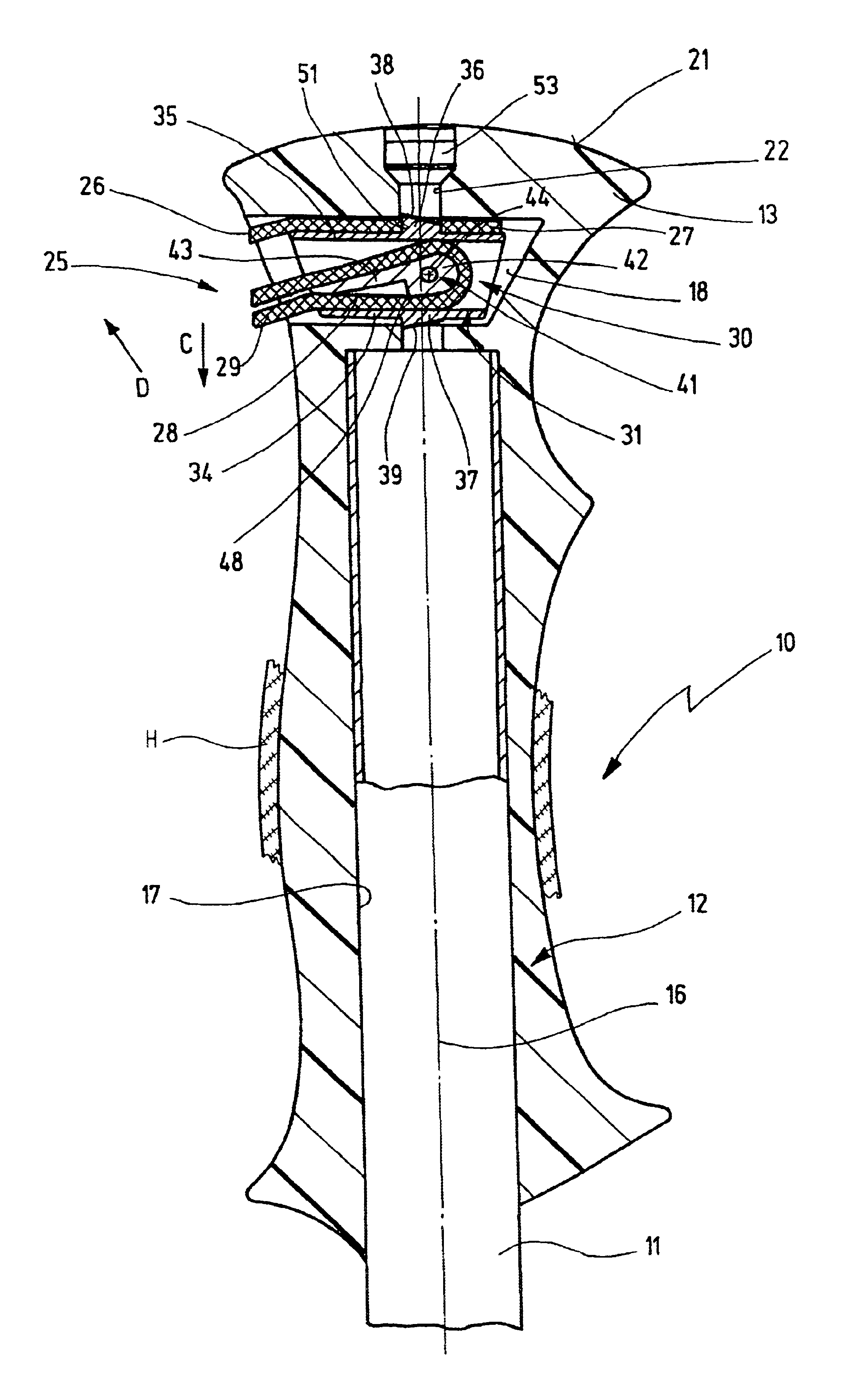
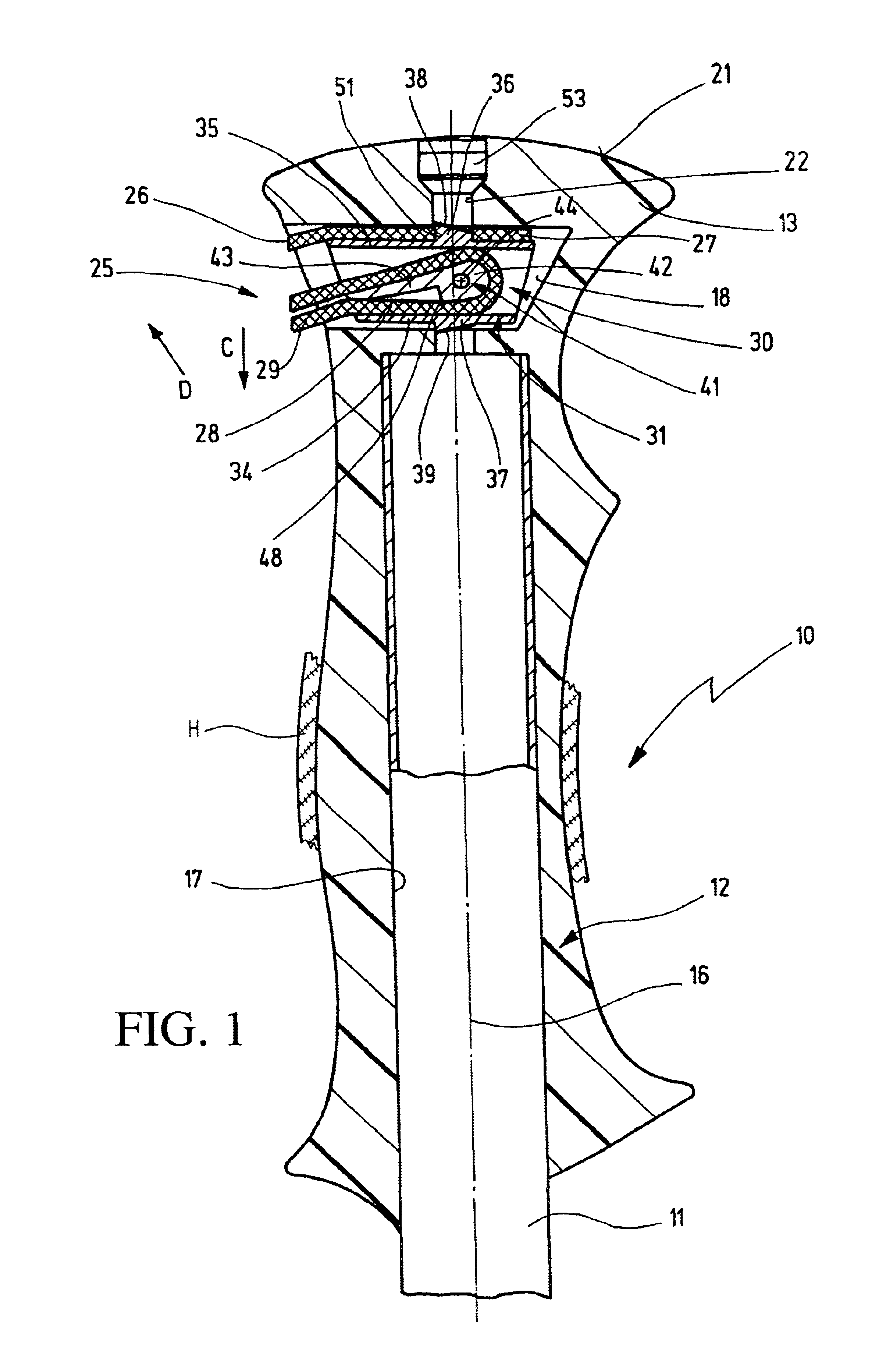
A cane handle 10, which has a handle body 12 with an upper handle end element 13 is fixedly attached to a cane tube 11, as is represented in the drawings. The handle body consists, for example, of an inner body of a hard plastic material, for example polyamide, to which then a layer H of an easy-grip material, for example natural caoutchouc, a cork-elastomer mixture, or the like, has been applied.

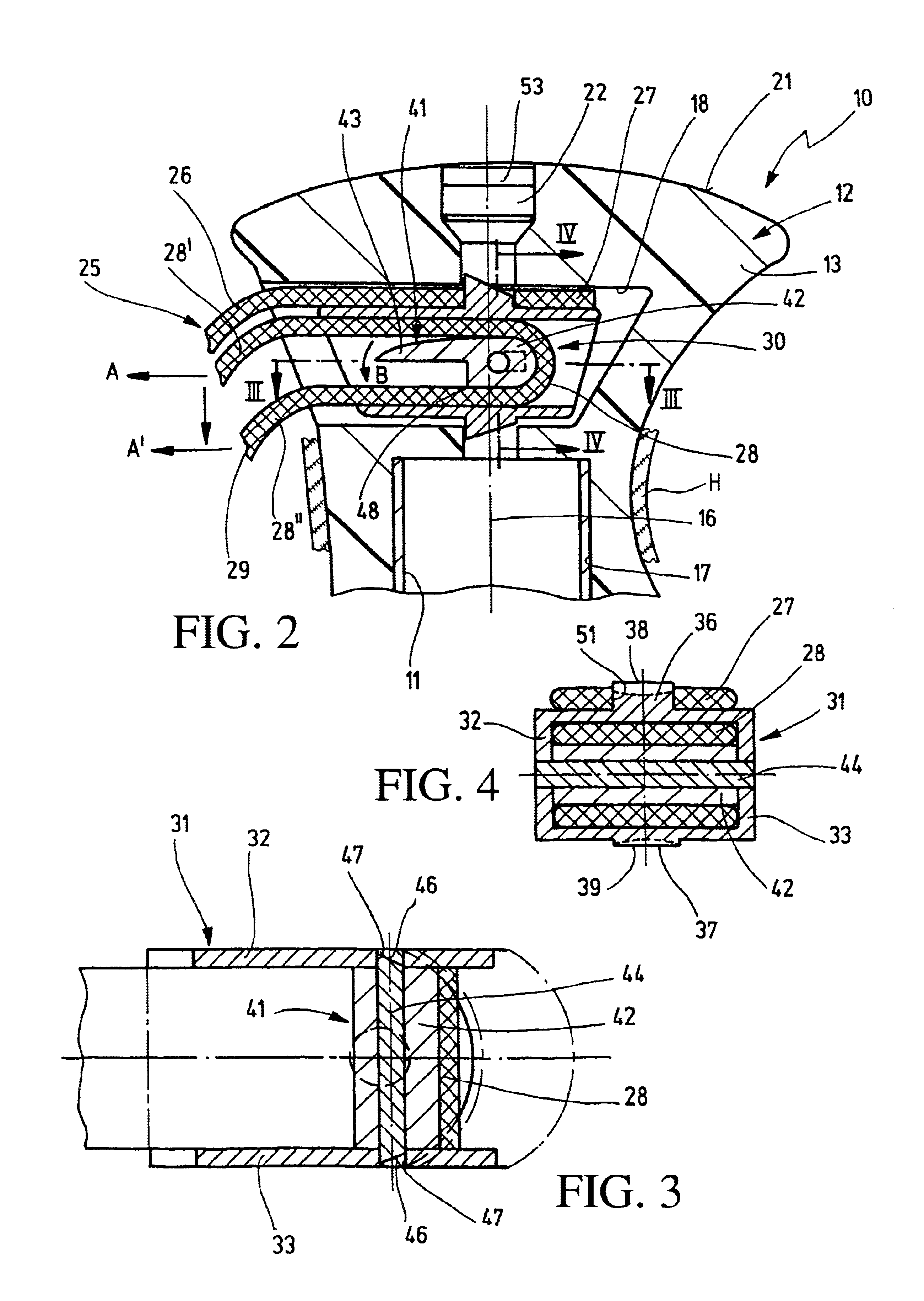
The handle body 12 has a recess 18, which is laterally inserted above the end of a hollow chamber 17, which is concentric in relation to the cane tube axis 16 for receiving the cane tube 11 and which, in cross section, has a substantially rectangular cross section in the transverse direction, and a substantially trapezoidal cross section in the longitudinal direction. The depth of the recess 18 is preferably approximately ¾ of the cane handle width, or of the cane handle diameter in this area. Starting at the cane handle front face 21, a stepped bore 22, which is concentric in respect to th...


PUM


Abstract

The invention relates to a cane handle comprising a hand strap attached to the top end of the handle. Said strap forms a loop which has an adjustable length and can be fixed by means of a clamping device placed in the top end of the handle. Said clamping device comprises a clamping element which is placed in the top end of the handle and encircled by the loop. In order to adjust the hand strip more easily and to reduce the number of components required, the clamping element with the encircling section of the loop is set between an upper and a lower bearing surface, is placed in such a way that it pivots around an approximately horizontal axis, and has a clamping area which is eccentric in relation to the swivelling axis.

Description

FIELD OF THE INVENTIONThe present invention relates to a cane handle having a hand loop maintained in the area of the upper handle end piece, which is formed by a loop strip and whose loop length can be changed and which can be fixed in place by means of a clamping device arranged in the handle end piece, having a clamping element, which is arranged in the handle end piece, and around which the loop strip is wrapped.BACKGROUND OF THE INVENTIONIn connection with such a cane handle, known from DE 196 32 718 C2, the clamping element of the clamping device is axially indirectly movable via a rotatably seated arresting member, wherein the arresting member is movable by means of a rotatable actuating member, and is therefor axially movable by means of a screw thread. Therefore the clamping of the hand loop takes place between the arresting member, the clamping element and the bottom of the recess in the cane handle which contains the clamping device.With this construction, wherein the cla...

Claims


Application Information

Patent Timeline
IPC IPC(8): A63C11/00A63C11/22
CPCA63C11/222A45B2009/025A63C11/2224
Inventor LENHART, KLAUS
Owner LENHART KLAUS
Why Eureka
Try Eureka