
Articulated multi-hull water craft

a multi-hull, water craft technology, applied in the field of sailboats, can solve problems such as sudden stop planning, and achieve the effect of easy loading

Inactive Publication Date: 2005-02-08
AMORY JONATHAN
View PDF11 Cites 7 Cited by
  • Summary
  • Abstract
  • Description
  • Claims
  • Application Information

AI Technical Summary

Benefits of technology

It is a primary object of the present invention to produce a multi-hull vessel that is not size-limited in taking advantage of strong winds. It is a further object to provide such a vessel that is easily loadable on a transport vehicle for overland transport.
The way to achieving the primary object is to produce a multi-hull vessel that planes and can sustain strong winds without capsizing. The second object follows from using lightweight components and providing for their easy disassembly and assembly.
It is well-known that an important route to reducing drag on a vessel's hull is to cause it to plane, in which mode of movement it can be described as skimming across the water. When one is dealing with a catamaran, the basic nature of the boat works against planing. For one thing, the hulls of the traditional catamaran are round-bottomed, the antithesis of the flat, broad hull that facilitates planing at a low speed. If one simply replaces the traditional catamaran hulls with broad, flat hulls, the propensity of the leeward hull to dig into the water under heeling conditions can prevent the vessel from reaching a planing mode or, if it is planing, can cause it to suddenly cease planning.
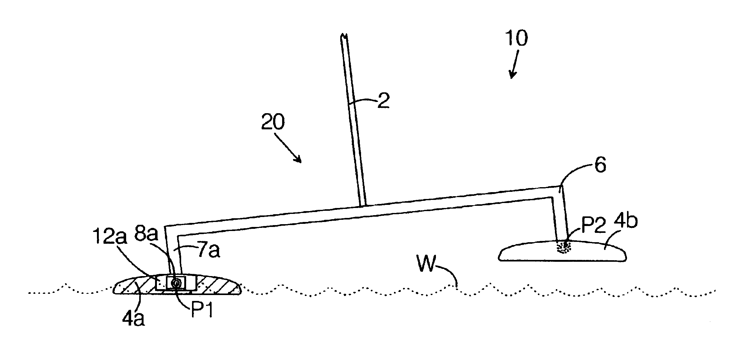
With the hulls pivotally coupled to the superstructure, the mast (and sail) can heel over under the force of wind while the flat-bottomed hulls remain parallel to the water. Consequently, planing is achievable at a relatively low speed, after which the drag, caused predominantly, in this context, by turbulence formation, is drastically reduced and the vessel can be driven very efficiently by the wind.
With a catamaran, the crew provide a very large righting moment as needed by shifting their weight to windward. In a boat constructed according to the invention, the combination of this very large righting moment and the independent articulation of the hulls enables the vessel to quickly reach planing speed. Further, with the platform and mast rotating along a longitudinal axis with respect to the hulls, the hulls continue to remain parallel to the water after planing speed is reached, regardless of the degree of heel of the mast. This is essential to the success of the design because of the tendency of the catamaran to lose its planing capacity should one of the (flat) hulls dig into the water. Since the planar hulls of the present invention always remain parallel to the water's surface, they are far more effective planing surfaces than existing planing hulls that need to allow for some heel.
The other feature that separates the catamaran of this invention from traditional catamarans is its transportability. Most sailing dinghies weigh around 140 pounds and must be transported overland with a trailer. This makes it difficult for one or two people to move them from home to the water and back in one afternoon. In contrast, the boat of the present invention can be disassembled and gathered together in a single, small elongated bundle that is easily loadable atop a standard-size automobile by one or two persons. Starting fully assembled, the prototype described above can be completely broken down and secured on a car in thirty minutes. The heaviest component is the platform, which when made of aluminum is 60 pounds or less and, when made of plastic, about 20% lighter.

Problems solved by technology

If one simply replaces the traditional catamaran hulls with broad, flat hulls, the propensity of the leeward hull to dig into the water under heeling conditions can prevent the vessel from reaching a planing mode or, if it is planing, can cause it to suddenly cease planning.

Method used


Image

  • Articulated multi-hull water craft
  • Articulated multi-hull water craft
  • Articulated multi-hull water craft

Examples


Embodiment Construction

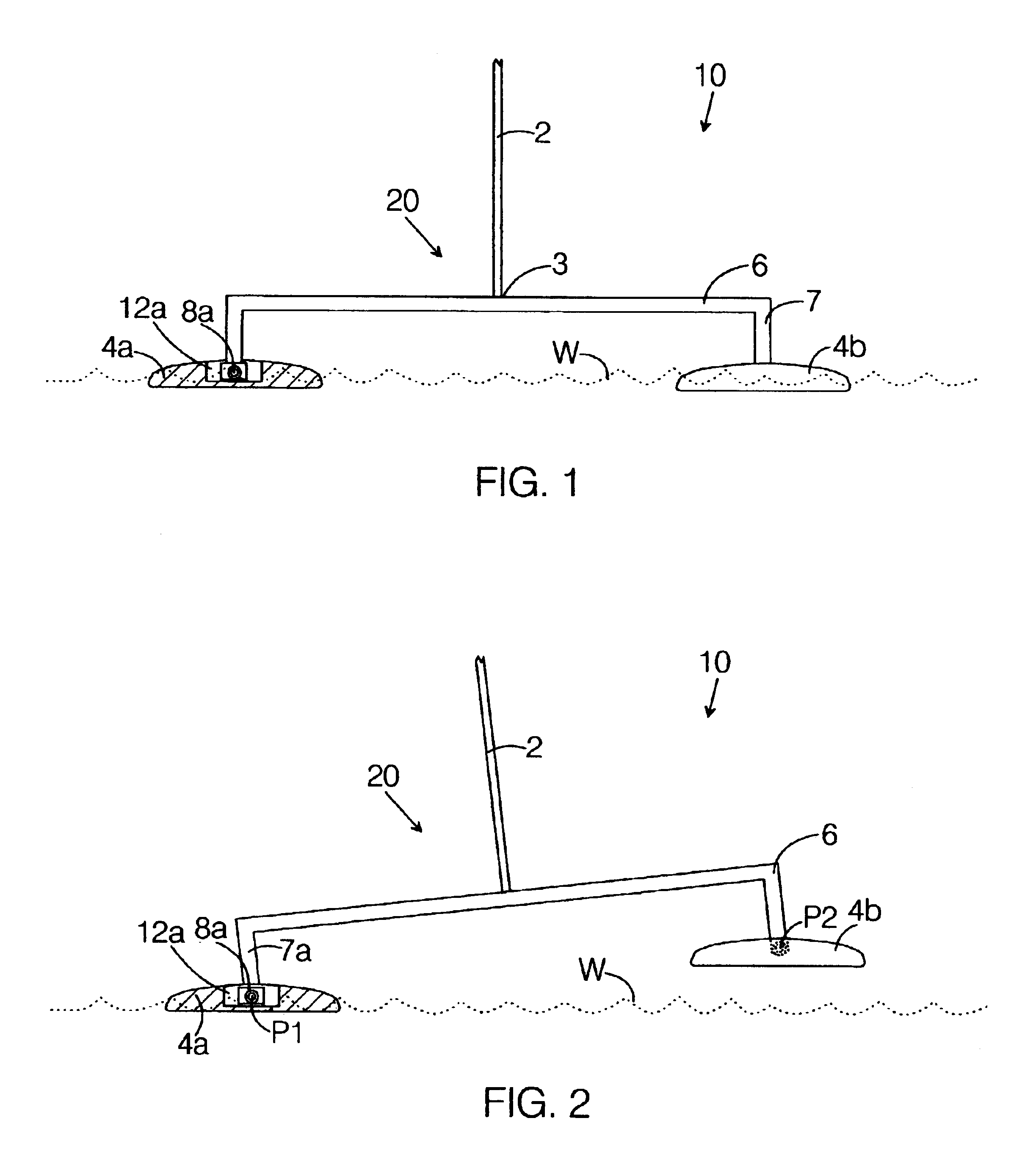
FIG. 1, FIG. 2, and FIG. 3 schematically show a catamaran vessel 10 according to the present invention, the vessel 10 including a first hull 4a, a second hull 4b, and a superstructure 20, where both the first hull 4a and the second hull 4b are flat on the bottom. The superstructure 20 includes a platform 6 and a mast 2, the mast 2 having a lower mast end 3 rigidly connected to the platform 6.

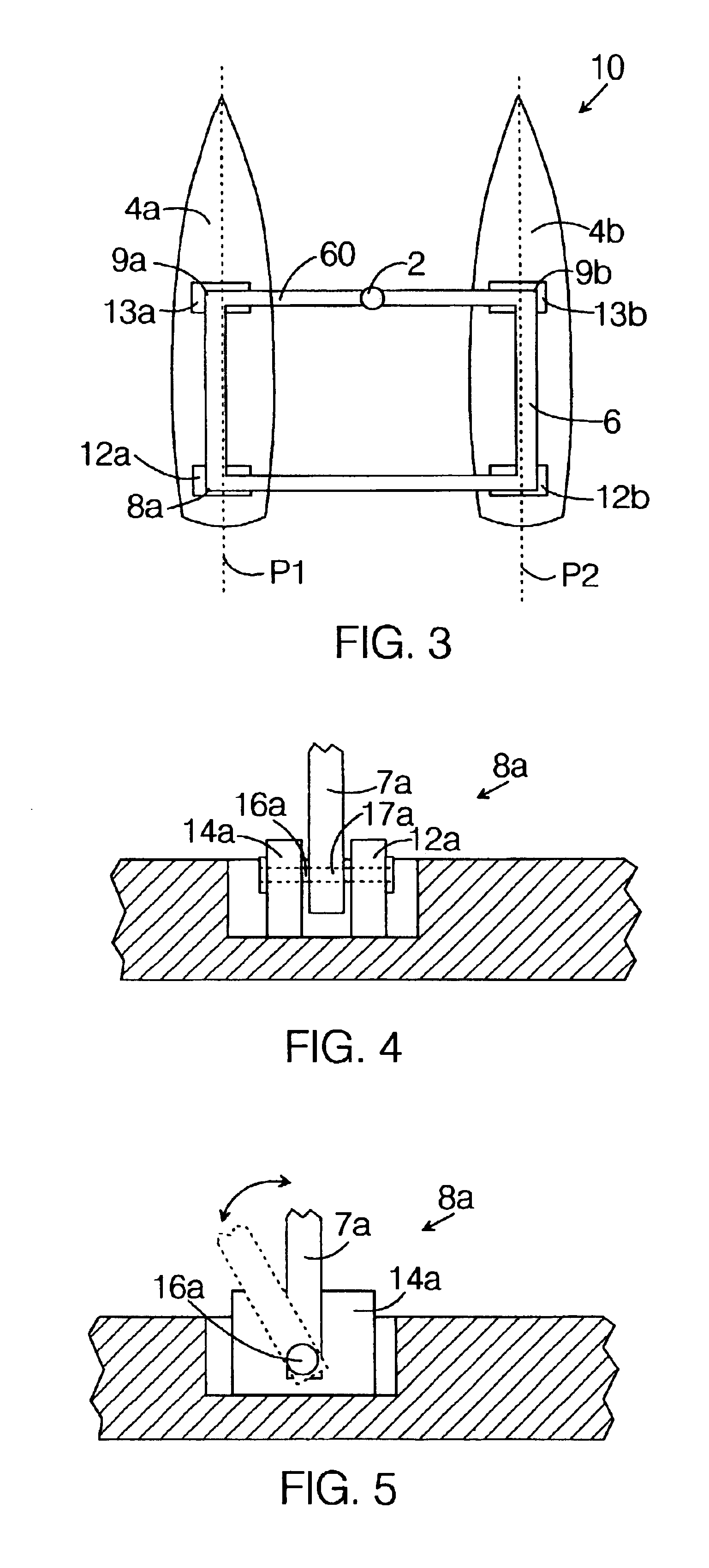
FIG. 1 shows the vessel 10 under a condition of zero wind; FIG. 2 shows the vessel 10 in a heeling configuration, under wind, illustrating the articulation between the superstructure 20 and the first hull 4a and the second hull 4b; and FIG. 3 is a topdown view of the vessel 10 that shows that the platform 6 has four sides, one of which is a mast-support beam 60. The mast-support beam 60 is the leading edge of the platform 6.

Because of the bilateral symmetry of the vessel 10, it is only necessary to describe one side of it. FIG. 3 shows the first hull 4a to have a first forward platform mount 13a...


PUM


Abstract

A multi-hull vessel capable of planing. The vessel has a rigid superstructure that is rotatably linked to flat-bottomed hulls. As the vessel heels, the pivotable connection between the superstructure and the hulls allows the superstructure to heel over while the hulls remain oriented so that their bottoms are parallel to the water surface. This allows the multi-hull vessel to plane at relatively low speeds without risking the consequences of a leeward planar hull digging into the water. Further, the vessel is made of lightweight components and configured to be assembled and disassembled in a short time by a single individual, and to be easily lifted and carried atop an automobile for overland transport.

Description

BACKGROUND OF THE INVENTION1. Field of the InventionThe present invention relates to the field of sailboats having more than a single hull, such as catamarans and trimarans. More particularly, the invention relates to a design modification that enhances the practicable speed that can be obtained from a small multi-hull sailboat. More particularly yet, the invention relates to such a modification that enhances the ability of the boat to plane.2. Prior ArtMany serious sailors seek very high performance in a sailing dinghy. Ideally, the dinghy is relatively inexpensive and is easily loaded on top of a vehicle and transportable overland. Unfortunately, the highest-performance sailing dinghies, such as the WindRide RAVE, are both expensive and difficult to transport. Although the most popular relatively-low-cost sailing dinghy, the LAZER, is fast, it is not extremely fast and, furthermore, it is cumbersome to transport.There are two main design approaches to increasing the speed at which...

Claims


Application Information

Patent Timeline
Patent Type & Authority Patents(United States)
IPC IPC(8): B63B1/20B63B1/16B63B1/00B63B1/12
CPCB63B1/121B63B1/125B63B1/20B63B2035/009B63B2001/145B63B2001/204B63B2001/045
Inventor AMORY, JONATHAN
Owner AMORY JONATHAN
Learn More