
Fuse relay box apparatus, methods and articles of manufacture

a technology of fuse relay and box apparatus, applied in the direction of relays, electrical apparatus construction details, coupling device connections, etc., can solve the problems of bringing their own complications, requiring more space for separate boxes for fuses and relays, and requiring more bulky wiring to the boxes

Inactive Publication Date: 2005-02-01
TYCO ELECTRONICS LOGISTICS AG (CH)
View PDF5 Cites 27 Cited by
  • Summary
  • Abstract
  • Description
  • Claims
  • Application Information

AI Technical Summary

Benefits of technology

The present invention comprises fuse relay box apparatus, methods and articles of manufacture. The preferred embodiments comprise a cover and power distribution module base. Fuses, relays and diodes (referred to herein as “electrical components”) may be installed upon the base. A cover seal may also be used in certain preferred embodiments. Both the cover and any seal help protect the components installed on the base from the environment.

Problems solved by technology

Separate boxes for fuses and relays require more space.
Additionally, separate boxes may require more bulky wiring to the boxes, as the fuse wires and any harnesses likely require a separate path to a fuse box from the path taken by relay wires and any harnesses to a relay box.
Fuse relay boxes, however, may bring their own complications.
Thus, any changes to fuse placement and / or fuse wiring placement in the box, or relay placement, and / or relay wiring placement in the box, can only be made with difficulty, and would require reconfiguration of the entire box.
Because of the limited reconfiguration potential of these fuse relay boxes (which occasionally includes diodes as well, leading to yet another level of complication), these boxes are vehicle specific.
They cannot be used in different vehicle models.
Additionally, a fixed configuration box often lacks mounting flexibility because the box requires a specific mounting on the vehicle.
Once design of that mounting is set, there is little or no ability to modify or move that mounting to accommodate new wiring and fuse or relay requirements.

Method used


Image

  • Fuse relay box apparatus, methods and articles of manufacture
  • Fuse relay box apparatus, methods and articles of manufacture
  • Fuse relay box apparatus, methods and articles of manufacture

Examples


Embodiment Construction

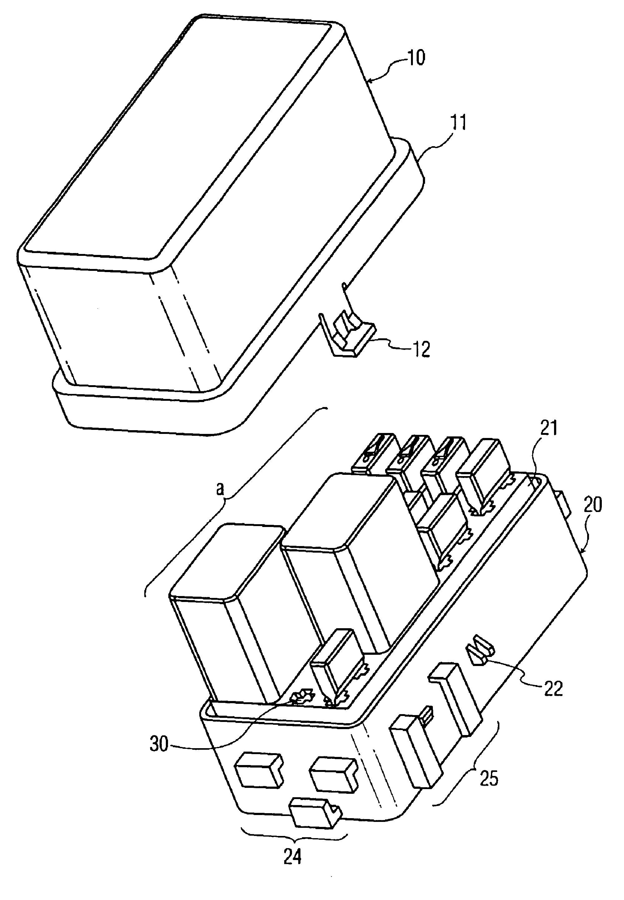
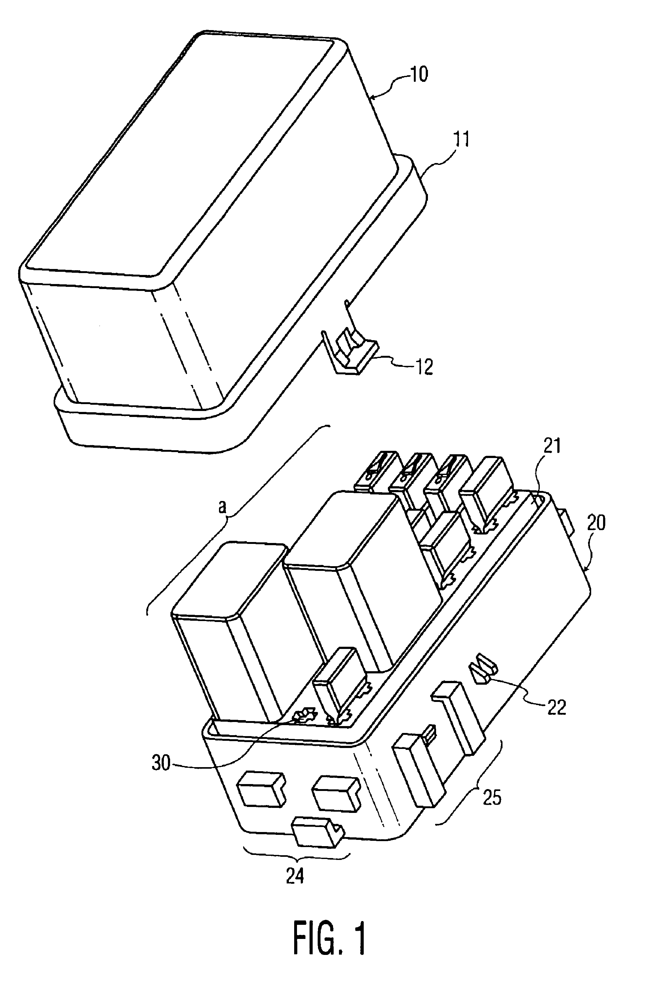
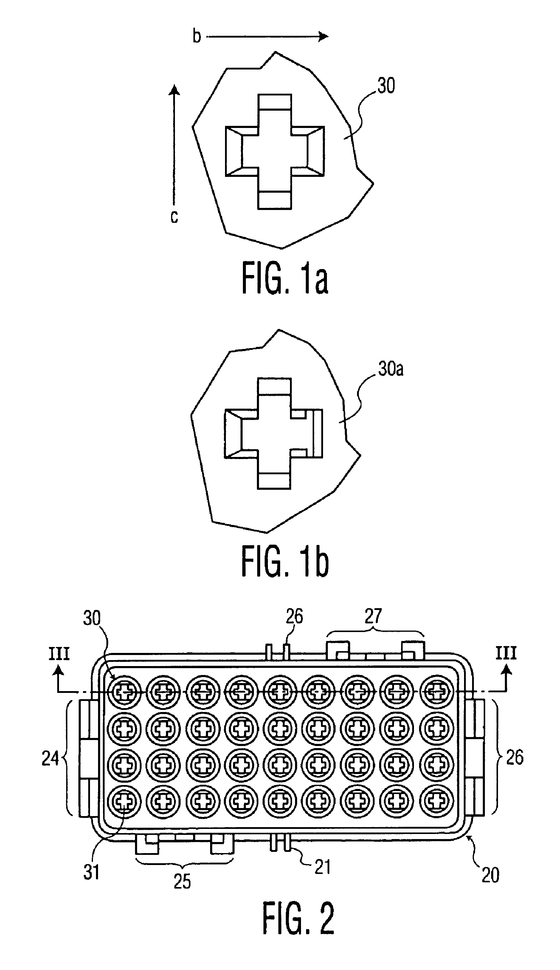
FIG. 1 shows a preferred embodiment with installed electrical components a. The contacts of the components are installed within various vertical channels of the embodiment, which are adapted to receive the contacts from electrical components as well as mating terminals for those contacts. Also seen is the top of a single unused channel 30. Each channel has a cross shape, such as shown in the isolated view of FIG. 1a, which receives a contact blade from the component in the slot along the direction shown by the arrow b (the “blade direction.”) The slot of each cross along the direction shown by the letter c (the “lateral direction”) is provided for removal of the terminal by means as known in the art. In other preferred embodiments, one or more channels may have an additional slot across the end of a leg in the blade direction and parallel to the lateral direction for mounting diodes, as shown by FIG. 1b, which is a view of isolated channel 30a. However, the presence of these slots, ...


PUM


Abstract

Fuse relay box apparatus, methods and articles of manufacture are shown. A fuse relay box comprises a cover and base, with optional seal. The base comprises a number of channels adapted for use by either a fuse or relay. Some channels may be useable by a diode as well. Terminals for the contacts of these components are connected to the contacts of the components through the channels. Mounting flexibility is also provided so the box is either side or bottom mounted.

Description

FIELD OF THE INVENTIONThe present invention relates to electrical components. More particularly, the present invention relates to electrical component housings such as fuse relay boxes and the like.BACKGROUND OF THE INVENTIONThe use of a housing, or box, in vehicles for electrical components such as fuses and relays has become fairly common. These mixed use boxes (known as fuse relay boxes) provide an advantage by decreasing the space required in the vehicle's internals. Separate boxes for fuses and relays require more space. Additionally, separate boxes may require more bulky wiring to the boxes, as the fuse wires and any harnesses likely require a separate path to a fuse box from the path taken by relay wires and any harnesses to a relay box.Fuse relay boxes, however, may bring their own complications. Placing fuses and relays in a single box is often accomplished through engineering specific areas of the box for a specific fuse or relay component. Wiring connecting those fuse-spe...

Claims


Application Information

Patent Timeline
Patent Type & Authority Patents(United States)
IPC IPC(8): H01H85/00H01H85/20H01H50/02
CPCH01H85/2045H01H50/02H01H2085/208
Inventor BOYD, KENNETH S.
Owner TYCO ELECTRONICS LOGISTICS AG (CH)
Learn More