
Systems and methods for identifying and mapping conduit location

a technology of system and method, applied in the field of subsurface object identification mechanisms, can solve the problems of delay in excavation projects, labor-intensive and costly, and achieve the effect of efficient and less labor-intensiv

Inactive Publication Date: 2005-02-01
VERIZON PATENT & LICENSING INC +1
View PDF28 Cites 226 Cited by
  • Summary
  • Abstract
  • Description
  • Claims
  • Application Information

AI Technical Summary

Benefits of technology

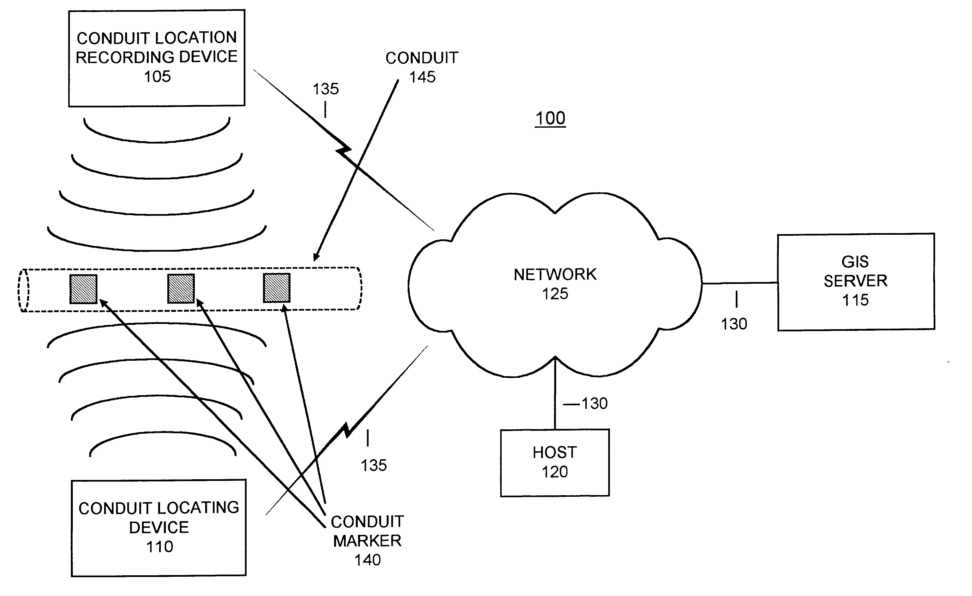
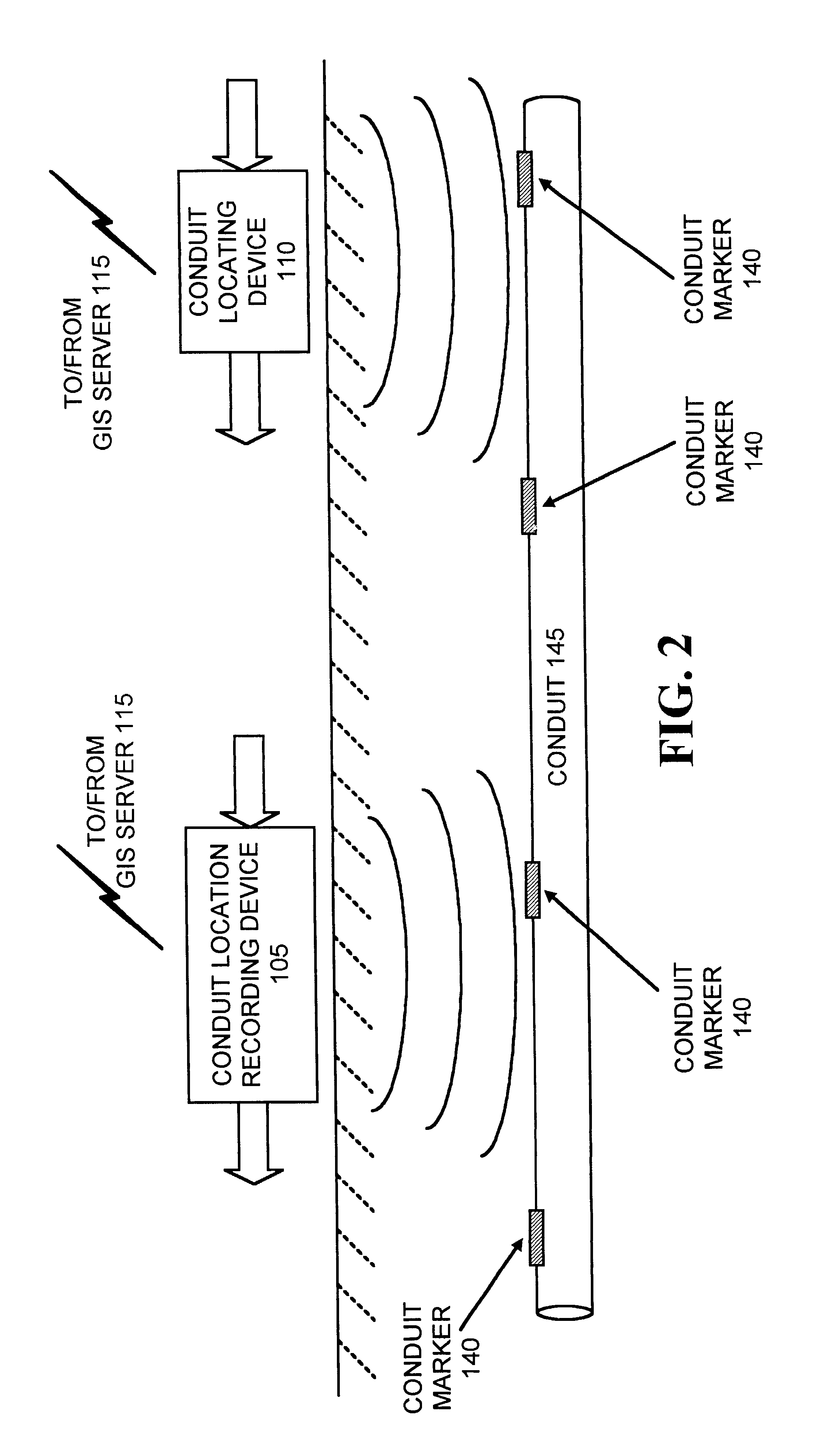
Systems and methods consistent with the present invention address this need and others by providing mechanisms that can identify, locate and map subsurface objects, such as conduits that may include cables, pipes and ducts, in an efficient and less labor intensive manner. Systems and methods consistent with the present invention can identify markers, such as Radio Frequency Identifier (RFID) tags or magnetic markers that are affixed to buried or subsurface objects and can determine the geo-location of the identified markers. Marker identification and geo-location data can then be transmitted, via a wireless network, to a central data storage facility, such as a data server, for storage. The stored subsurface object data can be retrieved by interested entities such as utility companies that are excavating a particular geographic area containing one or more subsurface objects.

Problems solved by technology

As is apparent, this “dig safe” process can be both labor-intensive and costly, and can cause delays in excavation projects.

Method used


Image

  • Systems and methods for identifying and mapping conduit location
  • Systems and methods for identifying and mapping conduit location
  • Systems and methods for identifying and mapping conduit location

Examples


Embodiment Construction

The following detailed description of the invention refers to the accompanying drawings. The same reference numbers in different drawings identify the same or similar elements. Also, the following detailed description does not limit the invention. Instead, the scope of the invention is defined by the appended claims.

Systems and methods consistent with the present invention provide mechanisms for identifying, locating and mapping subsurface objects, and storing subsurface object identification and location data in a central database that can be accessed via a wireless communications network. Subsurface objects can be identified, consistent with the present invention, through the use of markers such as RFID tags or magnetic markers, that are affixed to buried or subsurface objects.

Exemplary System

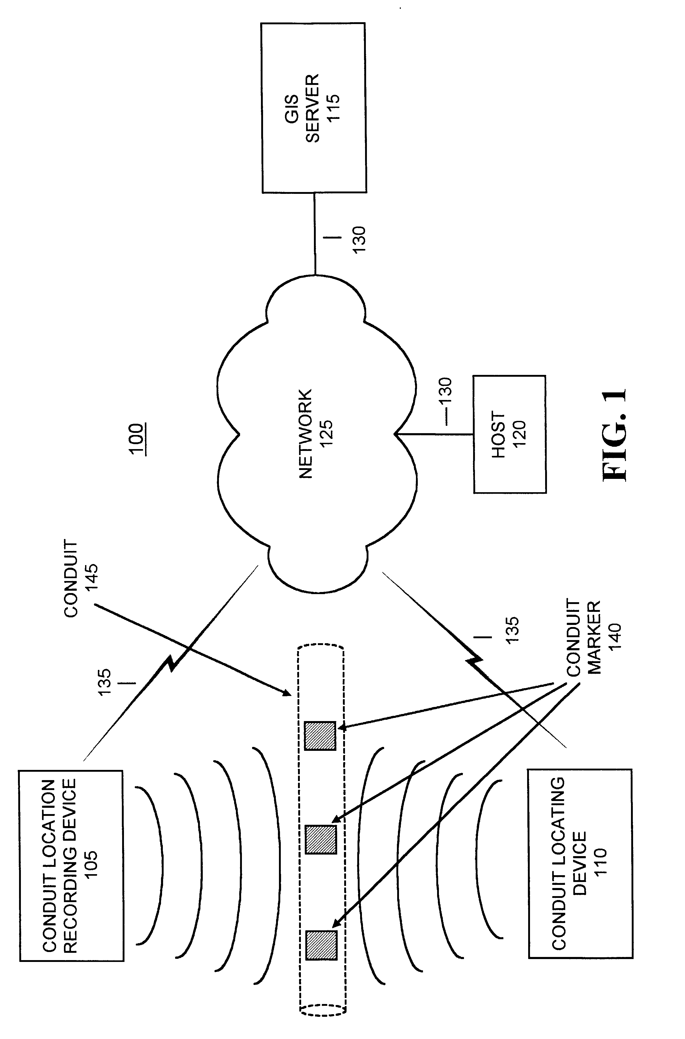
FIG. 1 illustrates an exemplary system 100, consistent with the present invention, for identifying and mapping conduits. System 100 may include a conduit location recording device 105, a cond...


PUM


Abstract

A system (100) for mapping an underground object (145) includes a conduit location recording device 105 and a server (115). The conduit location recording device (105) senses an underground object (145), a unique identifier being associated with the sensed underground object (145), and determines a location of the underground object (145). The conduit location recording device (105) transmits, via a communications network (125), the unique identifier and determined location to the server (115) for storage in a database.

Description

FIELD OF THE INVENTIONThe present invention relates generally to subsurface object identification mechanisms and, more particularly, to systems and methods for identifying, locating and mapping subsurface objects.BACKGROUND OF THE INVENTIONUtility companies often need to excavate in order to lay new conduits, such as cables, pipes or ducts, or in order to repair existing conduits. To avoid disrupting the underground equipment of other utility companies, an excavating utility company must now generally follow “dig safe” procedures. In such procedures, the excavating utility announces their digging plans to a central agency. This central agency inspects records that it maintains of the conduits of other utilities that have been buried in the area that is to be excavated. The central agency relays the planned excavation to any affected utilities. These affected utilities then send out people to mark the exact locations of their buried conduits by spraying paint at appropriate locations...

Claims


Application Information

Patent Timeline
IPC IPC(8): E21B47/022E21B47/02F16L1/06F16L1/11G01V15/00
CPCE21B47/02224G01V15/00F16L1/11E21B47/0232
Inventor ELLIOTT, BRIG BARNUMBURCHFIEL, JERRY
Owner VERIZON PATENT & LICENSING INC
Learn More