
Dimple pattern for golf balls

a golf ball and dimple pattern technology, applied in the field of golf balls, can solve the problems of poor flight characteristics, reduced percentage of golf ball surface, and ineffective dimple coverage of filling spaces with tiny dimples

Inactive Publication Date: 2005-02-01
ACUSHNET CO
View PDF11 Cites 39 Cited by
  • Summary
  • Abstract
  • Description
  • Claims
  • Application Information

AI Technical Summary

Benefits of technology

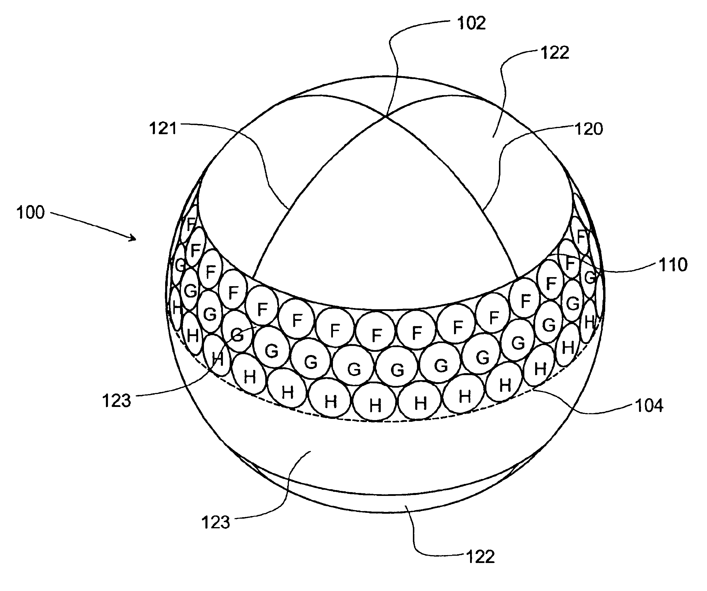
The present invention is directed to a golf ball having a dimpled surface that is subdivided into two or more distinct regions wherein different dimple placement schemes are used in different regions. A preferred embodiment has polar regions dimpled according to an octahedral-based dimple pattern and the equatorial region dimpled according to an icosahedron-based dimple pattern. This preferred embodiment has dimples of varying size, and has 388 total dimples.

Problems solved by technology

This is the primary source of drag for golf balls.
Dimple coverage gained by filling spaces with tiny dimples is not very effective, since tiny dimples are not good turbulence generators.
Most balls today still have many large spaces between dimples or have filled in these spaces with very small dimples that do not create enough turbulence at average golf ball velocities.
One of the drawbacks of such patterns is that many dimples placed within the pattern will follow parallel latitudinal paths resulting in aligned rows of dimples, which can provide poor flight characteristics.
Another drawback is that the multiple great circles reduce the percentage of the golf ball surface that can be filled with dimples.
However, this raises the trajectory and shortens the distance of the poles-horizontal orientation to match those of the pole-over-pole orientation, lowering the overall aerodynamic performance of the ball.

Method used


Image

  • Dimple pattern for golf balls
  • Dimple pattern for golf balls
  • Dimple pattern for golf balls

Examples


Embodiment Construction

FIGS. 1-4 illustrate an octahedron dimple pattern having 336 dimples. FIG. 1 shows the surface of the undimpled golf ball divided into eight identical spherical triangular regions 21, 22, 23, 24, 25, 26, 27, and 28 (not visible) that correspond to the faces of a regular octahedron. The boundaries of these regions comprise three mutually orthogonal great circle paths 10, 11, and 12.

In FIG. 2, region 22 has been filled with 42 dimples 13 arranged in three concentric triangular rings. The outer ring includes 21 dimples, the intermediate ring includes 15 dimples, and the inner ring includes 6 dimples. Preferably these dimples are sized and positioned in such a way as to maximize coverage of the ball surface. This grouping of dimples is the basic element that makes up the entire dimple pattern.

FIG. 3 shows the completed dimple pattern that is created by filling each of the other regions 21, 23, 24, 25, 26, 27, and 28 with an identical grouping of dimples as in region 22.

As shown in FIG. ...


PUM


Abstract

A golf ball having a dimpled surface that is subdivided into two or more distinct regions wherein different dimple placement schemes are used in different regions. A preferred embodiment has polar regions dimpled according to an octahedral-based dimple pattern and the equatorial region dimpled according to an icosahedron-based dimple pattern. This preferred embodiment has dimples of varying sizes and has 388 total dimples.

Description

BACKGROUND OF THE INVENTION1. Field of the InventionThe present invention is directed to a golf ball and, more particularly, to a golf ball having an improved dimple pattern.2. Description of the Related ArtSoon after the introduction of the smooth surfaced gutta percha golf ball in the mid nineteenth century, players observed that the balls traveled further as they got older and more gouged up. The players then began to roughen the surface of new golf balls with a hammer to increase flight distance. Manufacturers soon caught on and began molding non-smooth outer surfaces on golf balls, and eventually began to manufacture golf balls having dimples formed in the outer surface. Conventional dimples are depressions that act to reduce drag and increase lift. These dimples are formed where a dimple wall slopes away from the outer surface of the ball, forming the depression.One method of packing dimples on a golf ball divides the surface of the golf ball into eight spherical triangles cor...

Claims


Application Information

Patent Timeline
Patent Type & Authority Patents(United States)
IPC IPC(8): A63B37/00
CPCA63B37/0006A63B37/0004A63B37/00065
Inventor MORGAN, WILLIAM E.AOYAMA, STEVEN
Owner ACUSHNET CO
Learn More