
Slant entry well system and method

a well system and well technology, applied in the direction of drilling pipes, directional drilling, borehole/well accessories, etc., can solve the problems of limited production and use of methane gas from coal deposits, affecting the recovery of subsurface resources, etc., to achieve efficient production and removal of entrapped wells, and eliminate or reduce disadvantages and problems

Inactive Publication Date: 2005-02-01
EFFECTIVE EXPLORATION
View PDF267 Cites 60 Cited by
  • Summary
  • Abstract
  • Description
  • Claims
  • Application Information

AI Technical Summary

Benefits of technology

The present invention provides a slant entry well system and method for accessing a subterranean zone from the surface that substantially eliminates or reduces the disadvantages and problems associated with previous systems and methods. In particular, certain embodiments of the present invention provide a slant entry well system and method for efficiently producing and removing entrained methane gas and water from a coal seam without requiring excessive use of radiused or articulated well bores or large surface area in which to conduct drilling operations.
Embodiments of the present invention may provide one or more technical advantages. These technical advantages may include the formation of a plurality of slanted well bores and drainage patterns to optimize the area of a subsurface formation which may be drained of gas and liquid resources. This allows for more efficient drilling and production and greatly reduces costs and problems associated with other systems and methods.
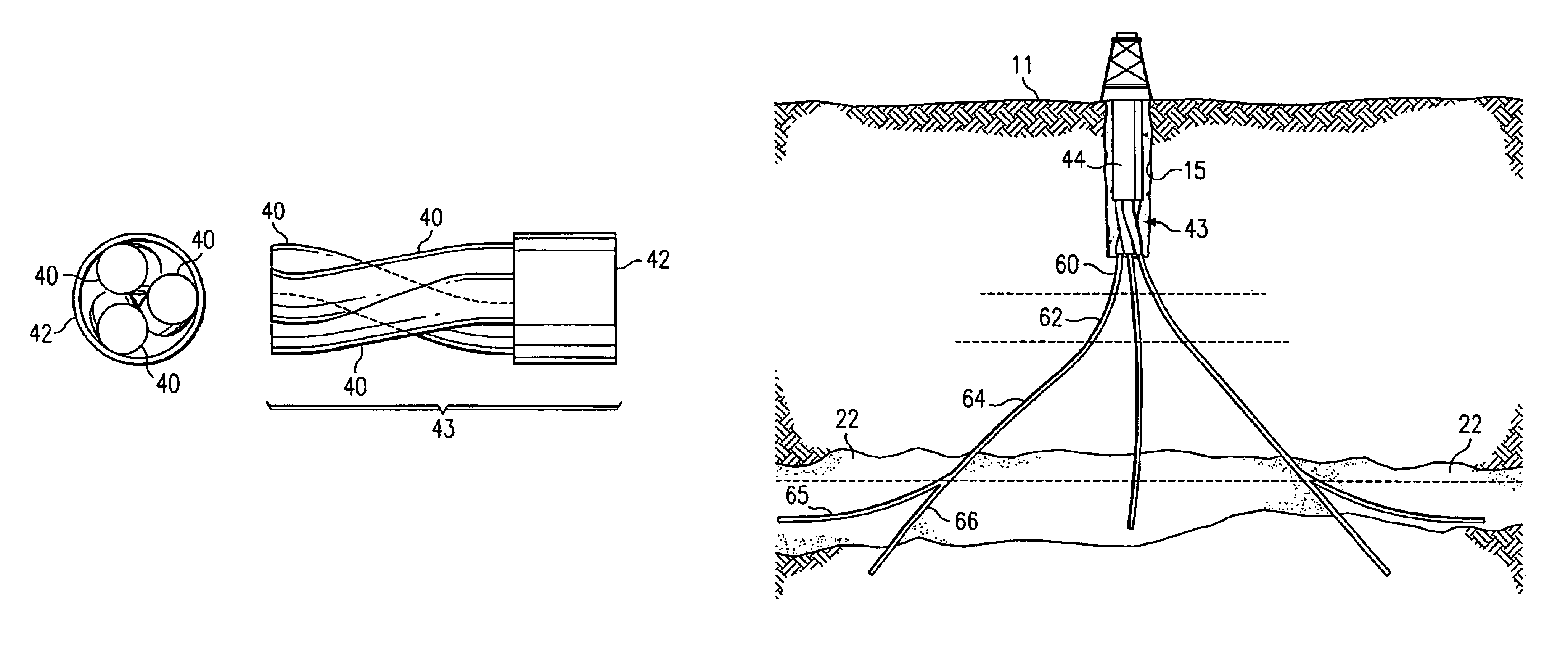
Another technical advantage includes providing a method for orienting well bores using a guide tube bundle inserted into an entry well bore. The guide tube bundle allows for the simple orientation of the slant well bores in relation to one another and optimizes the production of resources from subterranean zones by optimizing the spacing between the slanted well bores.

Problems solved by technology

Limited production and use of methane gas from coal deposits has occurred for many years.
Substantial obstacles, however, have frustrated more extensive development and use of methane gas deposits in coal seams.
The foremost problem in producing methane gas from coal seams is that while coal seams may extend over large areas of up to several thousand acres, the coal seams are fairly shallow in depth, varying from a few inches to several meters.
Thus, while the coal seams are often relatively near the surface, vertical wells drilled into the coal deposits for obtaining methane gas can only drain a fairly small radius around the coal deposits.
Further, coal deposits are not amenable to pressure fracturing and other methods often used for increasing methane gas production from rock formations.
As a result, once the gas easily drained from a vertical well bore in a coal seam is produced, further production is limited in volume.
Such horizontal drilling techniques, however, require the use of a radiused well bore which presents difficulties in removing the entrained water from the coal seam.
The most efficient method for pumping water from a subterranean well, a sucker rod pump, does not work well in horizontal or radiused bores.
While the use of subterranean methods allows water to be easily removed from a coal seam and eliminates under-balanced drilling conditions, they can only access a limited amount of the coal seams exposed by current mining operations.
The limitations of underground rigs limits the reach of such horizontal holes and thus the area that can be effectively drained.
In addition, the degasification of a next panel during mining of a current panel limits the time for degasification.
As a result, many horizontal bores must be drilled to remove the gas in a limited period of time.
Furthermore, in conditions of high gas content or migration of gas through a coal seam, mining may need to be halted or delayed until a next panel can be adequately degasified.
These production delays add to the expense associated with degasifying a coal seam.

Method used


Image

  • Slant entry well system and method
  • Slant entry well system and method
  • Slant entry well system and method

Examples


Embodiment Construction

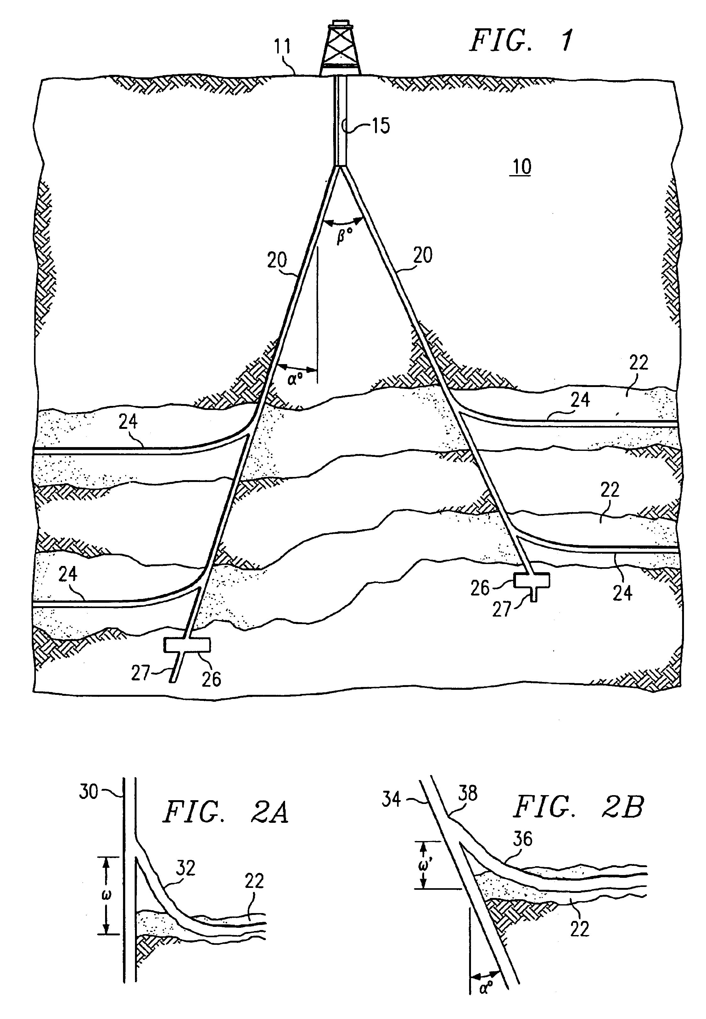
FIG. 1 illustrates an example slant well system for accessing a subterranean zone from the surface. In the embodiment described below, the subterranean zone is a coal seam. It will be understood that other subterranean formations and / or low pressure, ultra-low pressure, and low porosity subterranean zones can be similarly accessed using the slant well system of the present invention to remove and / or produce water, hydrocarbons and other fluids in the zone, to treat minerals in the zone prior to mining operations, or to inject or introduce fluids, gases, or other substances into the zone.

Referring to FIG. 1, a slant well system 10 includes an entry well bore 15, slant wells 20, articulated well bores 24, cavities 26, and rat holes 27. Entry well bore 15 extends from the surface 11 towards the subterranean zone 22. Slant wells 20 extend from the terminus of entry well bore 15 to the subterranean zone 22, although slant wells 20 may alternatively extend from any other suitable portion ...


PUM


Abstract

A guide tube bundle includes two or more guide tubes. Each guide tube includes a first aperture at a first end and a second aperture at a second end. The longitudinal axis of the first aperture of each guide tube is offset from the longitudinal axis of the second aperture of the guide tube Furthermore, the guide tubes are configured longitudinally adjacent to each other and are twisted around one another.

Description

TECHNICAL FIELD OF THE INVENTIONThe present invention relates generally to systems and methods for the recovery of subterranean resources and, more particularly, to a slant entry well system and method.BACKGROUND OF THE INVENTIONSubterranean deposits of coal contain substantial quantities of entrained methane gas. Limited production and use of methane gas from coal deposits has occurred for many years. Substantial obstacles, however, have frustrated more extensive development and use of methane gas deposits in coal seams. The foremost problem in producing methane gas from coal seams is that while coal seams may extend over large areas of up to several thousand acres, the coal seams are fairly shallow in depth, varying from a few inches to several meters. Thus, while the coal seams are often relatively near the surface, vertical wells drilled into the coal deposits for obtaining methane gas can only drain a fairly small radius around the coal deposits. Further, coal deposits are not ...

Claims


Application Information

Patent Timeline
IPC IPC(8): E21B43/30E21B43/00
CPCE21B43/305E21B43/006
Inventor ZUPANICK, JOSEPH A.
Owner EFFECTIVE EXPLORATION
Learn More