Piston for an internal combustion engine

Inactive Publication Date: 2005-01-25
HITACHI UNISIA AUTOMOTIVE
View PDF4 Cites 7 Cited by
  • Summary
  • Abstract
  • Description
  • Claims
  • Application Information

AI Technical Summary

Benefits of technology

It is accordingly an object of the present invention to provide a piston that is free from the above-described problem, i.e., that can prevent the swirl introduced into the cylinder from being obstructed by the cavity that is formed in the crown face so as to constitute a combustion chamber, thereby improving the combustion efficiency of the engine.

Problems solved by technology

However, the piston of the above-described kind encounters a problem that the cavity constitutes an obstacle to the swirl and decreases the intensity of the swirl since the traveling direction of the swirl and the longitudinal center axis of the cavity do not coincide with each other.

Method used


Image

  • Piston for an internal combustion engine
  • Piston for an internal combustion engine
  • Piston for an internal combustion engine

Examples


Embodiment Construction

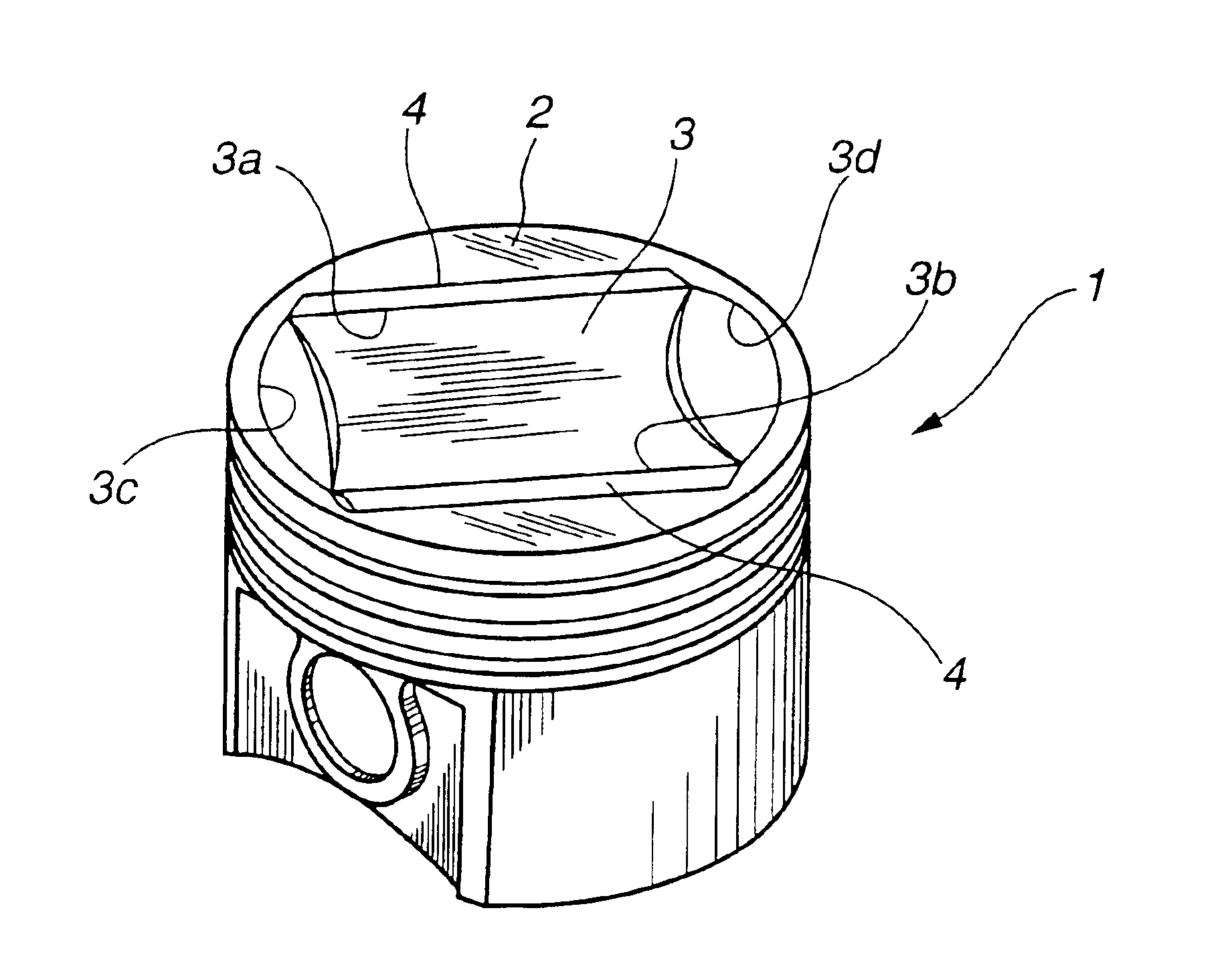
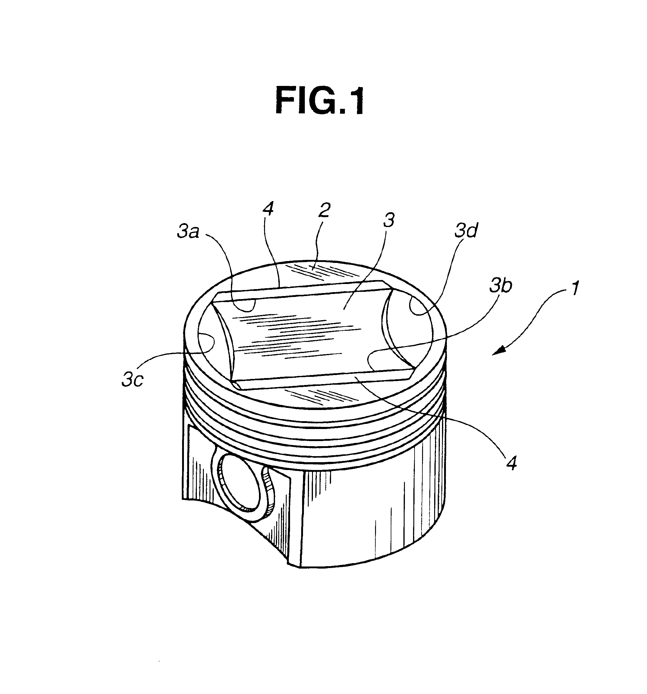
Referring first to FIGS. 1 and 2, a piston that reciprocates within a cylinder of an internal combustion engine is generally indicated by 1. The piston 1 has a crown 2 that is formed with a cavity 3 at a top face or crown face thereof.

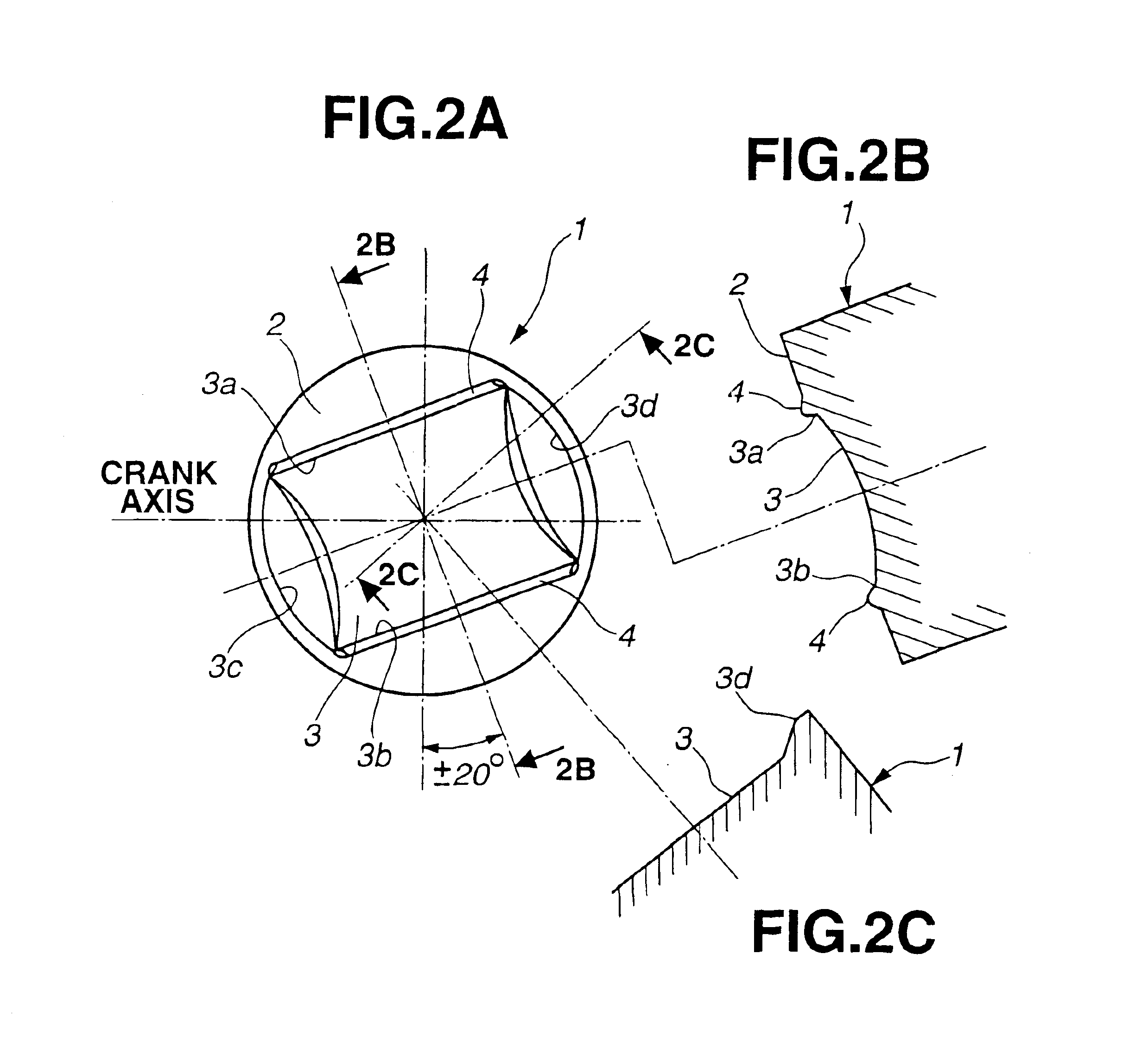
The cavity 3 has at the crown face of the crown 2 an open end consisting of parallel, straight longitudinal side edges 3a, 3b and part-circular edges 3c, 3d connecting between the opposite ends of the side edges 3a, 3b, respectively. The side edges 3a, 3b are parallel to a center axis that forms 20° with a crank axis and diametrically opposed in a way as to be nearly equidistant from the center of the crown face of the crown 2 (i.e., the center axis of the piston 1) and have terminal ends located adjacent the circumferential periphery of the piston 1.

Namely, the cavity 3 is formed so as to have a longitudinal direction or longitudinal center axis that forms 20° with a crank axis or an axis of a piston pin (not shown).

Further, the bottom of the cavity 3...


PUM


Abstract

A piston for an internal combustion engine is provided. The engine has an intake port through which an intake air is introduced into the cylinder in a way as to produce a swirl that travels along while whirling about an axis transversal to an axis of the cylinder. The piston has at a crown face thereof a cavity that has a part-cylindrical bottom. The cavity has a longitudinal center axis extending obliquely to a crank axis so that the longitudinal center axis of the cavity nearly coincides with an axis along which the swirl travels within the cylinder.

Description

BACKGROUND OF THE INVENTIONThe present invention relates to a piston for an internal combustion engine, particularly of the kind having a cavity at a crown face thereof.A piston of the above-described kind is disclosed in Japanese Patent Provisional Publication No. 2000-018041.The piston disclosed in the Publication has at a crown face thereof indentations or valve pockets that are opposed to intake and exhaust valves, respectively and a cavity that is provided continuously from the valve pockets so as to constitute a combustion chamber, which cavity has a longitudinal axis in parallel with a crank axis.SUMMARY OF THE INVENTIONIn an engine of the kind adapted to burn a mixture of a lean air-fuel ratio, it has been practiced to provide an intake port with an intake control valve (swirl control valve) and close the intake control valve at low-load of the engine thereby producing a swirl, i.e., a flow of air-fuel mixture that travels along while whirling about a horizontal axis or an a...

Claims


Application Information

Patent Timeline
IPC IPC(8): F02B31/00F02B31/08F02B17/00F02B31/06F02F3/26F02B23/06F02B23/08F02F3/24
CPCF02B17/00F02B31/06F02B31/085Y02T10/146F02F3/26Y02T10/12
Inventor SARUWATARI, MASAYUKINAKAMURA, YOSHITATSU
Owner HITACHI UNISIA AUTOMOTIVE
Why Eureka
Try Eureka