Eureka AIR delivers breakthrough ideas for toughest innovation challenges, trusted by R&D personnel around the world.

High Q angular rate sensing gyroscope

a sensing gyroscope and high q technology, applied in the direction of turning-sensitive devices, acceleration measurement using interia forces, instruments, etc., can solve the problems of low sensitivity, low q value, low signal-to-noise ratio of the voltage output of the sensing element, etc., to reduce the flexure of the resonator wall, improve the accuracy and q value of the resonator, and suppress unwanted oscillation modes

Inactive Publication Date: 2005-01-25
WATSON INDUSRIES
View PDF17 Cites 11 Cited by
  • Summary
  • Abstract
  • Description
  • Claims
  • Application Information

AI Technical Summary

Benefits of technology

Therefore, it is an objective of the present invention to provide a uniformly polarized piezoelectric resonator. It is another object of the present invention to improve the accuracy and Q value of the resonator by providing a plurality of actuators that are contoured to conform to areas of substantially uniform stress in the walls of the resonator and which are located on the resonator so as to maximize the flexure of the resonator wall per unit volt applied to the resonator. Similarly, it is yet another object of the invention to suppress unwanted modes of oscillation through the proper arrangement of actuators and pick-offs on the piezoelectric resonator. Another objective of the present invention is to provide a pick-off structure that minimizes error due to undesirable stresses and deformations present in a resonating element. Another objective is to reduce the inherent variations in output voltage sensed at the nodal pick-offs due to fluctuations in the environmental conditions in which the gyroscope is operating. Yet another objective is to provide more reliable electrical connections between the actuators and pick-offs and the electronics used to filter and process the electrical signals received from and sent to the actuators and pick-offs, respectively.
With the aforesaid background in mind, improved pick-off and actuator conductors have been developed which minimize error in the angular rate of change reported by an angular rate sensing gyroscope. Furthermore, angular rate sensing gyroscopes incorporating the present invention have a more uniform voltage response and are provided with conductive leads that are relatively resistant to damage.
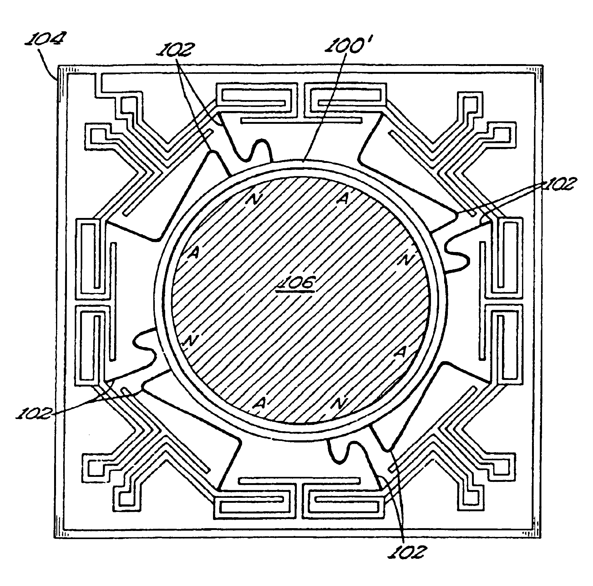
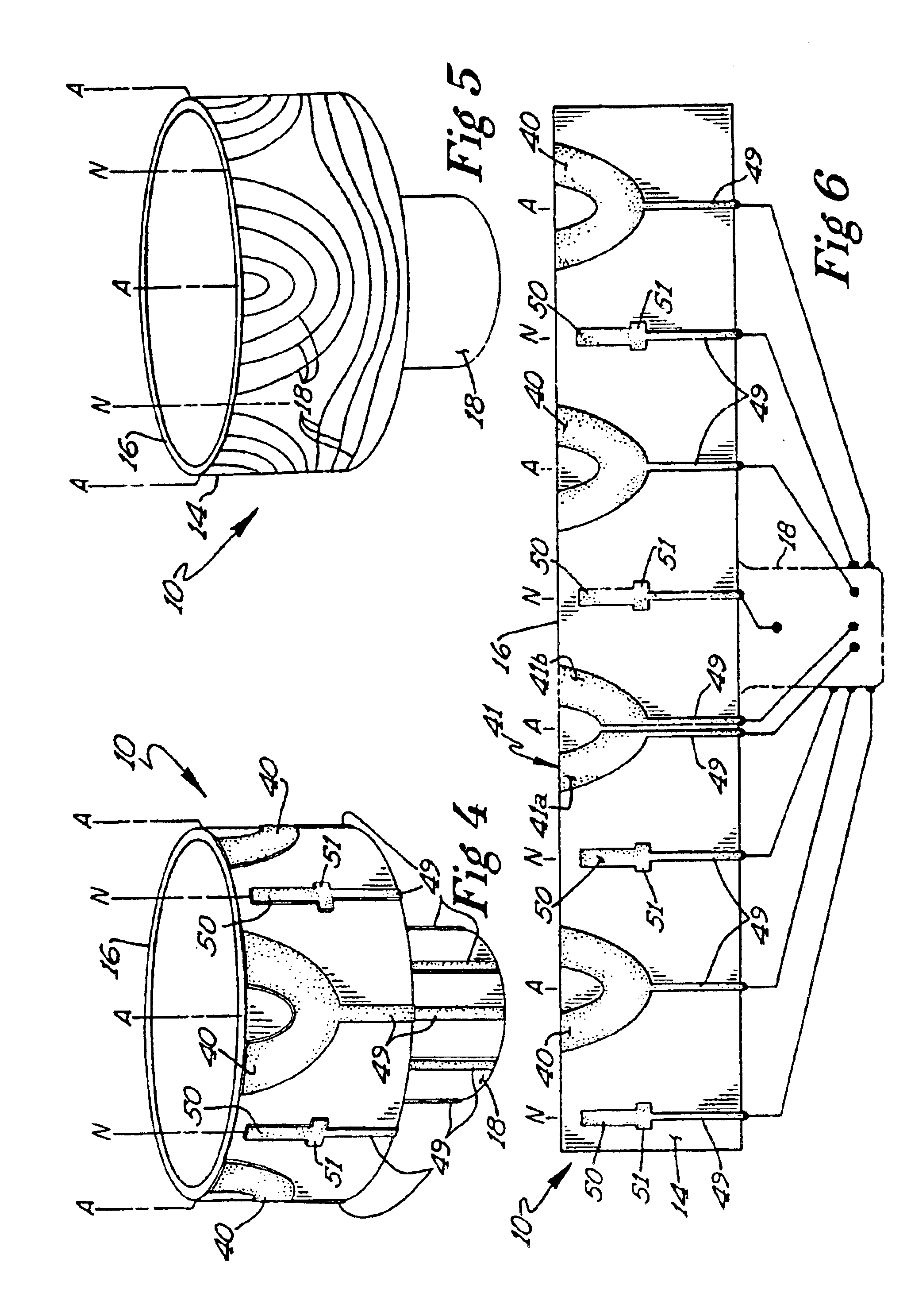
A resonating element according to the present invention is characterized by the ability to vibrate in a predetermined mode of oscillation defined by a plurality of stable nodes and anti-nodes. Actuator conductors of the present invention are applied to the surface of said resonating element substantially at the anti-nodes and pick-off conductors are applied substantially at the nodes. The advantageous arrangement of the actuator and pick-off conductors on the anti-nodes and nodes, respectively, results in a more sensitive and efficient angular rate sensing gyroscope.
In another embodiment of the present invention, a resonating element having a polygonal cross-section has a predetermined number of improved conductive elements applied to the sides or faces thereof. The conductive elements are applied to the resonating element at areas of the sides or faces that are subject to drive motion stress which, when differentially sensed, is substantially zero or minimal when angular rate sensing gyroscope is rotationally stationary. The conductive elements of this embodiment may further be provided with a voltage balancing conductor applied to the resonating element in electrical communication with the conductive elements so as to zero or minimize net voltage signals sensed by said conductive elements when the angular rate sensing gyroscope is rotationally stationary. It is important to note that differential sensing using conductive elements that are applied to substantially the entire length of the resonating element tends to damp out uniformly applied disturbances to the resonating element such as vibrations and magnetic fields.
Rate sensing gyroscopes are more accurate when the piezoelectric material of the resonating element has a uniform voltage response. A method of improving the uniform voltage response of a piezoelectric resonating element at a predetermined location of a solid resonating element having first and second opposing surfaces begins with the step of applying a thick or thin film conductor to the entire first surface of the resonating element. Next, an applied film conductor is applied to the entire second surface of the resonating element. The respective applied film conductors are then connected to a DC voltage source that applies a DC voltage of predetermined strength across the respective applied film conductors so as to uniformly modify the voltage response of the piezoelectric material of the resonating element over substantially the entire area of the piezoelectric material located between the respective applied film conductors. Finally, predetermined portions of the respective applied film conductors are removed to create a plurality of discrete applied film conductors arranged upon one or both of the surfaces of the resonating element as described above.
The useful life of a rate gyroscope comprising an axi-symmetrical resonating element is greatly improved by providing a plurality of applied film conductor leads which extend from each of the actuator conductors and pick-off conductors arranged upon the surface of the resonating element, to the base portion of the resonating element. The applied film conductor leads electrically connect the actuator conductors and pick-off conductors to circuitry for operating the angular rate sensing gyroscope. The use of applied film conductor leads in the place of fine wires reduces the amount of failures due to stress fracture of the wires. A suitable applied film conductor lead has a width between 1% and 4% of the diameter of the resonating element to which it is applied. Preferably, the electrical connections between the applied film conductor leads and the drive circuitry of the gyroscope are made at the base of the resonating element where there is substantially no vibration in the resonating element.

Problems solved by technology

These undesirable bending forces create voltage signals that may degrade the signal to noise ratio of the voltage output of the sensing elements and may indicate falsely that the angular rate sensor is being rotated about its sensitive axis.
Problems with angular rate sensors of the type patented by Varnham include a relatively low Q value, low sensitivity, and low accuracy.
In addition, the application of actuators and pick-offs across a range of stresses, in combination with non-uniform voltage responses in the piezoelectric materials, make it more difficult to force the resonator to oscillate in its desired mode.
Piezoelectric materials are not uniform in their voltage response and therefore it is frequently the case that a pick-off having a large surface area will sense net voltages skewed by an uneven voltage response of the piezoelectric material.
And because the actual voltages sensed by the pick-offs are quite small, voltage signal components due to uneven voltage responses frequently alter the signal to noise ratio of the sensed voltages to an extent that makes it difficult to determine accurately the rate and magnitude of rotation of the gyroscope.
Furthermore, because it is also frequently the case that the voltage response of respective areas of the piezoelectric materials that make up a resonator may vary independently with changes in the ambient temperature of the operating environment of the gyroscope, the noise to signal ratio of the sensed voltages may become further degraded.
A further problem can arise because, in general, piezoelectric materials are made up of many individual crystals that have been sintered together and given a particular polarity by the application of a strong DC voltage.
Where this polarization is performed over a discrete area of the piezoelectric material, such as over the surface of the resonator covered by the conductive patches of the actuators and pick-offs, the polarization of the material at the edges of the discrete area will not be in the desired direction and will therefore generate irregular voltage responses.
In addition, it is not uncommon that the piezoelectric material of the resonator will be subject to irregular stresses or flexure.
The combination of irregular stresses or flexure with uneven edge polarization may cause severe fluctuations in the accuracy and sensitivity of the angular rate sensor and may also lower the Q value of the system.
The small size of the connection wires 23 makes them weak and prone to frequent failure due to applied forces and internal stresses resulting from the ultrasonic wedge bonding processes that are typically used to make such small electrical connections.
In addition, the use of solder or solder-like materials on the resonator at the physical contact between the wire 23 and the resonator tend to interfere with the inducement and maintenance of the desired mode of oscillation, thereby lowering the Q factor of the system.

Method used


Image

  • High Q angular rate sensing gyroscope
  • High Q angular rate sensing gyroscope
  • High Q angular rate sensing gyroscope

Examples


Embodiment Construction

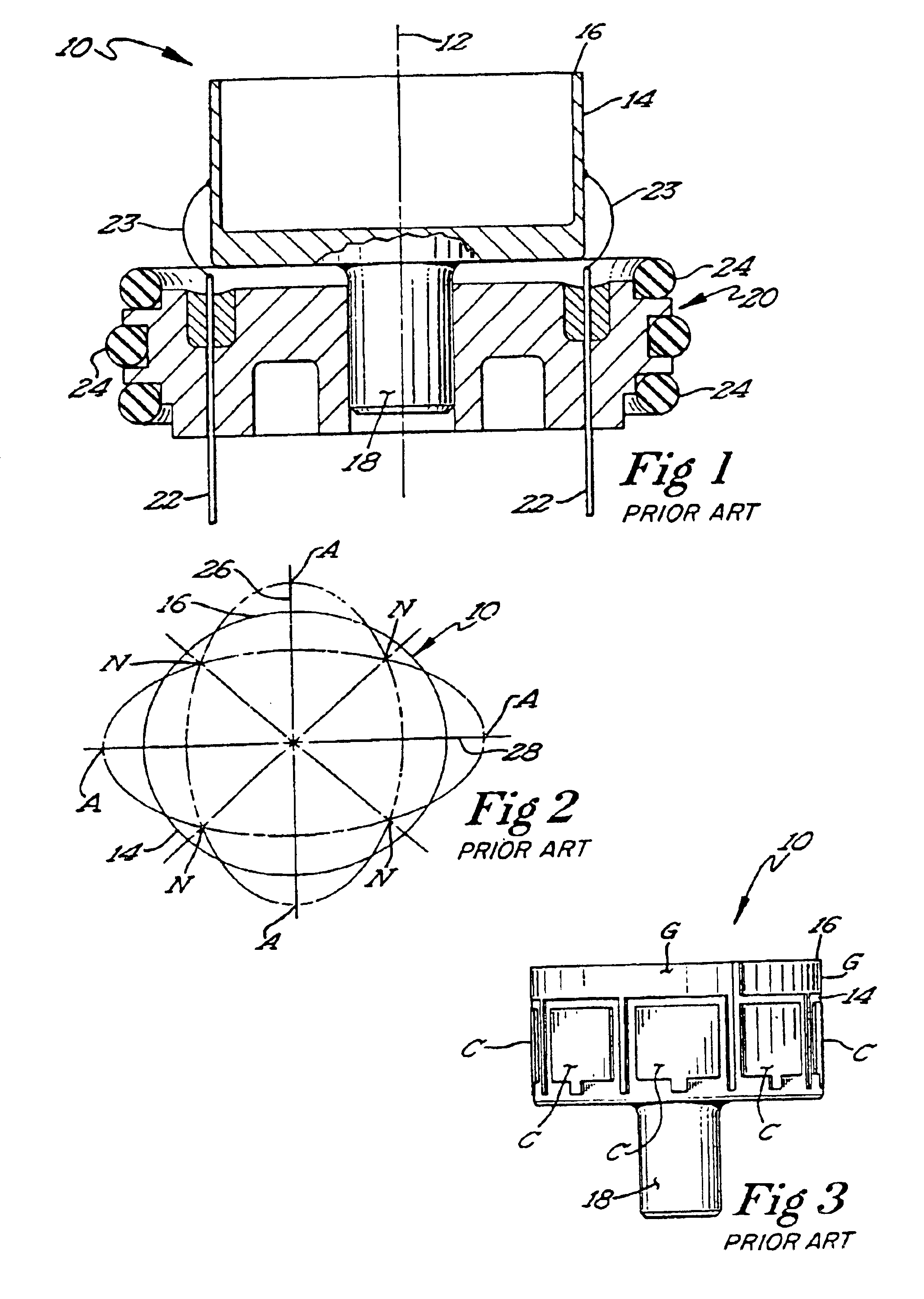
The preferred embodiment of the present invention may be used in conjunction with various types of resonating elements used in rate gyroscopes. However, the preferred embodiment of the present invention will be most fully described as applied to an axi-symmetric shell 10 such as the shell illustrated in FIGS. 1, 3-5a. Such a shell 10 may be caused to vibrate at a resonant frequency having a preferred mode of oscillation that is characterized by two nodal diameters (n=2) as illustrated in FIG. 2. It is to be understood that the improvements disclosed herein may have application outside of the specific embodiments described herein and are therefore not to be limited to just these embodiments.

Referring first to FIGS. 1, 3-5a, the shell 10 of the preferred embodiment is generally cylindrical and has an axis of symmetry indicated at 12. The upper portion of the shell 10 is a hollow cylinder having a relatively thin wall 14 with an upper edge 16. The lower portion or stem 15 of the shell ...


PUM


Abstract

A structure and arrangement for improving the accuracy and efficiency of an angular rate sensing gyroscope is herein disclosed. Voltage pick-off conductors are applied to an area of the surface of a resonating element of an angular rate sensing gyroscope that is subject to substantially zero stress when the gyroscope is rotationally stationary. Actuator conductors are similarly applied to a resonating element at a location bounded by areas of the resonating element subject to substantially uniform levels of stress when the gyroscope is rotationally stationary. A method for improving the voltage response of a piezoelectric resonating element is also disclosed.

Description

FIELD OF THE INVENTIONThe present invention is drawn to an angular rate sensor of the type utilizing an oscillating resonating element. More specifically, the present invention is drawn to the shape and placement of actuators and pick-offs upon resonating elements of angular rate gyroscopes.BACKGROUND OF THE INVENTIONRate gyroscopes operate on the principle of inertia. Standing waves are excited in a resonating element to produce a desired mode of oscillation having a predetermined number of nodes. The oscillations have an amplitude, a frequency, and an inherent oscillatory inertia that is independent of the linear and rotational inertia of the gyroscope itself. When the resonating element is rotated about its sensing axis, the oscillations will in large part maintain their absolute spatial orientation. However, in maintaining their absolute spatial orientation, the nodes that define the desired mode of oscillation will rotate with respect to the physical structure of the resonating...

Claims


Application Information

Patent Timeline
Patent Type & Authority Patents(United States)
IPC IPC(8): G01C19/56
CPCG01C19/567G01C19/5642
Inventor WATSON, WILLIAM S.
Owner WATSON INDUSRIES
Why Eureka
Eureka Blog
Learn More