
System for protecting and controlling substation main circuit components

a technology for substations and main circuits, applied in the field of system for protecting and controlling substation main circuit components, can solve the problems of large size of protection and control units, less cost-effectiveness, and wider installation space, and achieve the effect of reducing the volume of electric cables for communicating them

Inactive Publication Date: 2005-01-18
KK TOSHIBA
View PDF22 Cites 54 Cited by
  • Summary
  • Abstract
  • Description
  • Claims
  • Application Information

AI Technical Summary

Benefits of technology

[0019]Accordingly, it is an object of the present invention to provide an improved system for protecting and controlling substation main-circuit components in a substation, wherein all or almost all of the circuits and components including the driving circuits and transformer circuits for measuring current and voltage are digitized, and the volume of the electric cables for communicating them is reduced compared to those using analogue technique.

Problems solved by technology

(1) Electric cables and analogue information have been used in the substation main-circuit components and in the information transmission between the protecting-and-controlling units for protecting and controlling the substation main-circuit components. Therefore, the protecting-and-controlling units require as input and output circuits, contact input circuits and contact output circuits which can accommodate higher voltage and larger current compared to digital circuits. In addition, all the protecting-and-controlling units require input conversion units for transforming the currents and voltages into certain easily-handled levels, and analogue input circuits for converting the analogue values to digital values. Those requirements resulted in the protecting-and-controlling units of relatively large size and less cost-effectiveness.
(2) Although processing parts for protecting and controlling in the protecting-and-controlling units have become more compact due to the digitalization, the volumes of the hardware constituting the input and output circuits are still larger for isolation from the substation main-circuit components due to the cause described in (1) above, and large space is required for large volume of electric cables. Therefore, each one of the protecting unit and controlling unit for each main circuit must be contained in a separate chassis and must be independent, which has resulted in wider space required for installation.
(3) Since parallel connections for analogue information have been used between the main-circuit components and the protecting-and-controlling units, large volume of cables are required corresponding to the number of signals transmitted. Thus, cost of cables, of construction for cable pits and of cable installation have been enhanced, resulting in higher cost of the substation construction.
(4) Since the driving circuits for the substation main-circuit components and the transformer circuits for current and voltage measurement have had analogue technique, hardware sizes have been large, which has caused the sizes of the substation main-circuit components larger. Besides, work for assembling and connecting the circuits in the manufacturing factories and on the substation construction sites have required large manpower.
(5) Because of the reasons similar to those described in (4) above, real-time monitoring and automatic diagnosis of the substation main-circuit components have been difficult, which have resulted in insufficient information about the maintenance, and which have been an obstacle for manpower reduction.

Method used


Image

  • System for protecting and controlling substation main circuit components
  • System for protecting and controlling substation main circuit components
  • System for protecting and controlling substation main circuit components

Examples


eighth embodiment

[0246]An eighth embodiment of a system for protecting and controlling substation main-circuit components according to the present invention is now described with reference to FIG. 22. FIG. 22 is a block diagram of the eighth embodiment, showing the connecting relations between the merging unit and the sensor units. The protecting-and-controlling unit 23, the merging unit (MU) 39-3 and the sensor units (SUs) 28c-1 through 28c-n are similar to the corresponding units of the embodiments described above.

[0247]Sampling synchronization and time data adding are now discussed in detail. This embodiment corresponds to Pattern 2 shown in FIG. 3C as noted before.

[0248]As shown in FIG. 22, the point-to-point communication lines 40 (See FIGS. 17 and 18) have been eliminated through which the standard signals for synchronization and the time data might be sent from the merging unit 39-3 to the sensor units 28c-1 through 28c-n. Instead, one of the sensor units (the sensor unit 28c-1, for example) ...

ninth embodiment

[0261]A ninth embodiment of a system for protecting and controlling substation main-circuit components according to the present invention is now described with reference to FIGS. 23 through 26. FIG. 23 is a block diagram of the ninth embodiment, showing the connecting relations between the merging unit and the sensor units. The protecting-and-controlling unit 23, the merging unit (MU) 39-4 and the sensor units (SUs) 28d-1 through 28d-n are similar to the corresponding units of the embodiments described above.

[0262]Compared to the embodiment shown in FIG. 22, the transmission line 40-2 for sending standard signals for synchronization between the sensors has been eliminated as shown in FIG. 23,

[0263]The construction of the merging unit 39-4 is shown in FIG. 24, for example. Compared to the merging unit 39-2 shown in FIG. 20, the merging unit 39-4 of this embodiment shown in FIG. 24 has a synchronizing means 39h which is connected to the CPU 39b via the internal bus 39f. In this embodi...

tenth embodiment

[0286]A tenth embodiment of a system for protecting and controlling substation main-circuit components according to the present invention is now described with reference to FIGS. 27 and 28. FIG. 27 is a block diagram of the tenth embodiment. The protecting-and-controlling unit 23, the merging unit (MU) 39, the sensor units (SUs) 28-1 through 28-n and the component controlling-and-monitoring units (CMUs) 30-1 through 30-n are similar to the corresponding units of the embodiments described above.

[0287]As shown in FIG. 27, the merging unit 39 receives the standard signals for synchronization from the GPS receiver 41, and distributes a signal “SPT” which is a signal for time synchronization of AC electric values of the substation main-circuit components and for high precision (microsecond order) time adding to the sensor units 28-1 through 28-n. The merging unit 39 also distributes a time-adding standard signal “SOE” from the standard signals of the GPS receiver 41 to the protecting-and...


PUM


Abstract

The present invention relates to a system for protecting and controlling main-circuit components of an electricity transmission substation. The system includes devices for digital data output, protection-and-controlling, component controlling-and-monitoring, and communication. The digital data output devices input analogue AC electric values and output digital data. The protection-and-controlling devices input the data from the digital data output devices, and further control, monitor, and protect the substation main-circuit components. The component controlling-and-monitoring devices receive commands from the protection-and-controlling devices or from the substation controlling-and-monitoring equipment, and further control and monitor the substation main-circuit components. The devices for digital data output, the protection-and-controlling, and component controlling-and-monitoring are disposed near or within their corresponding substation main-circuit components.

Description

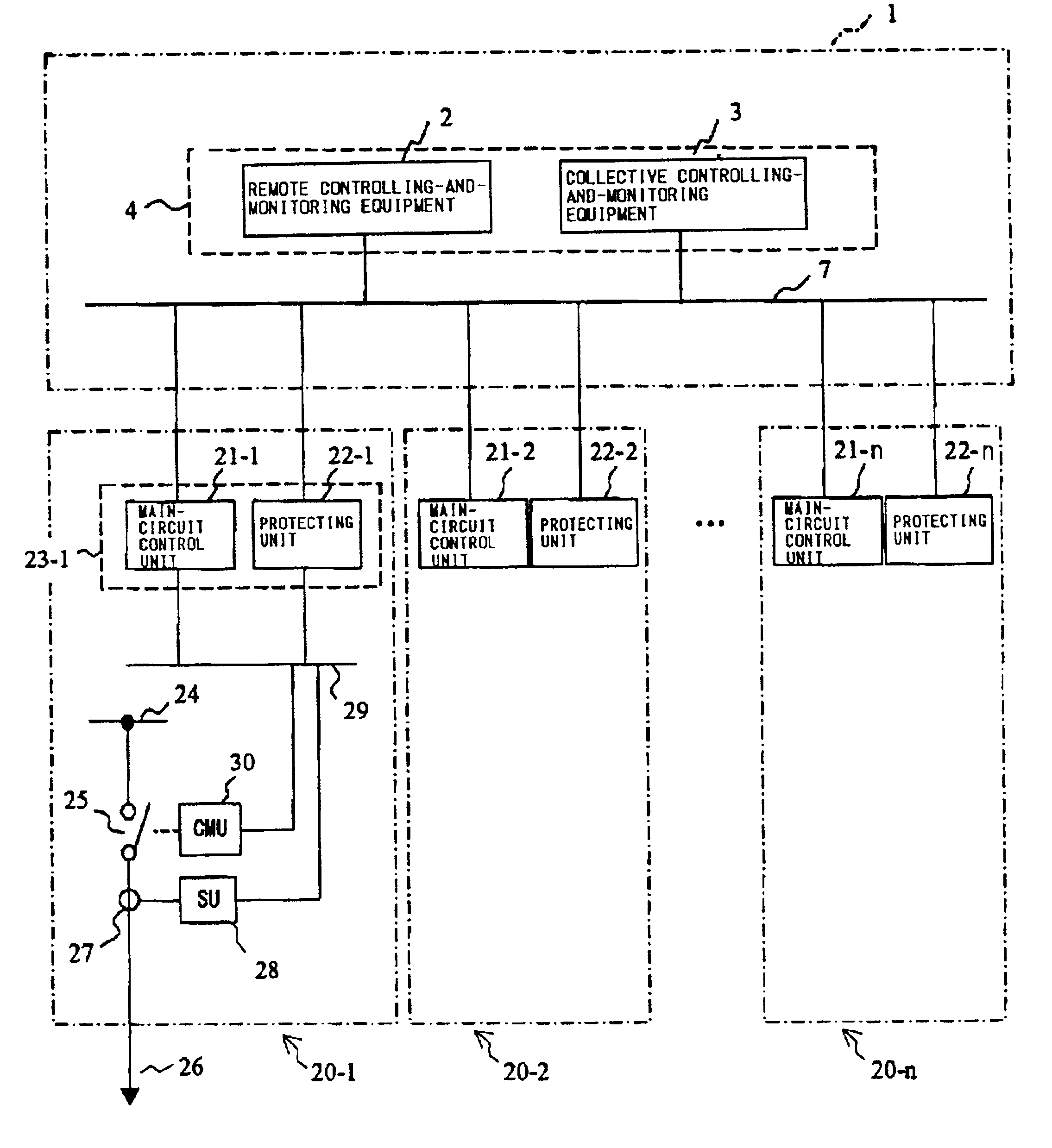
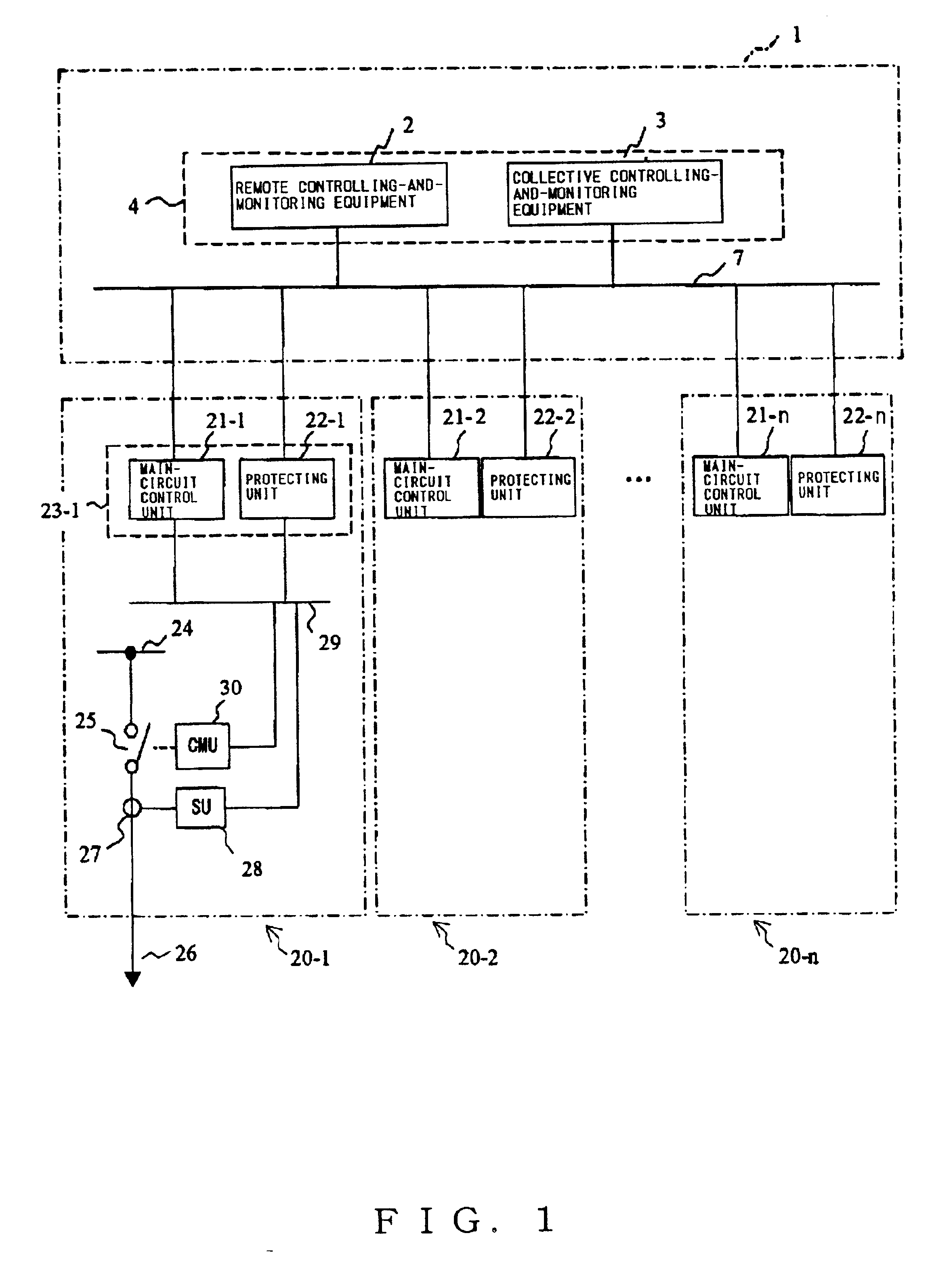
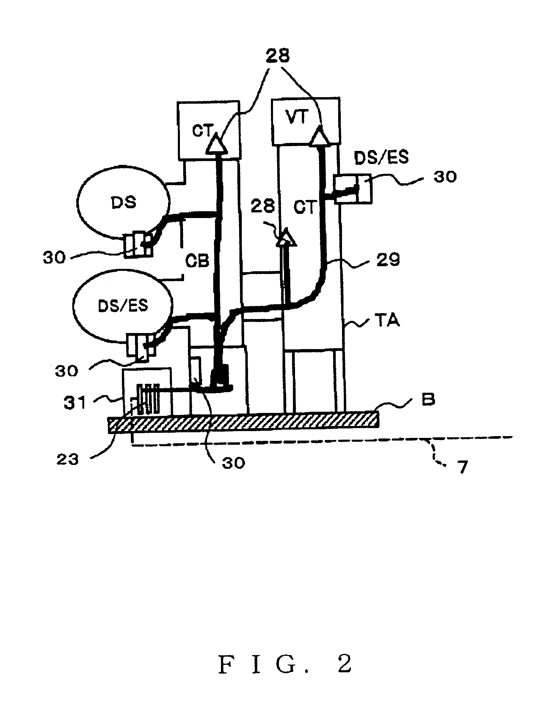
CROSS-REFERENCES TO RELATED APPLICATIONS[0002]This application is based upon and claims the benefit of priority from the prior Japanese Patent Applications No. 2001-33833, filed on Feb. 9, 2001 and No. 2001-321725 filed on Oct. 19, 2001; the entire contents of which are incorporated herein by reference.BACKGROUND OF THE INVENTION[0003]This invention is generally related to a system for protecting and controlling substation main-circuit components, and more particularly to a system including AC electric value sensors, analogue-to-digital converters and communication means for protecting and controlling substation main-circuit components.[0004]Now an example of prior-art system for protecting and controlling substation main-circuit components in a substation is discussed referring to FIG. 53. The system has digital operational processors and communication means. The substation has a main control building 1 which contains substation controlling-and-monitoring equipment 4 including a re...

Claims


Application Information

Patent Timeline
IPC IPC(8): H02H7/26H02H3/05H04L12/26H04L12/24H02H3/02H02J13/00
CPCH02H3/05H02H7/26H04L41/00H04L12/24H02H7/261
Inventor HAMAMATSU, KOICHIITO, TOKUOITO, HACHIDAISAMEDA, YOSHITOSAIDA, TOSHIYUKISUGA, NORIYOSHINAGASAKI, HIROMIMINAMI, YUUJINAKAJIMA, TAKASHIMARUYAMA, SHIROSAITO, MINORUTANAKA, TATSUJITAKAHASHI, MASAOTAMURA, SETSUOKOSAKADA, MASAYUKI
Owner KK TOSHIBA
Learn More