
Motion estimation and compensation for video compression

Inactive Publication Date: 2005-01-18
ALCATEL-LUCENT USA INC
View PDF4 Cites 30 Cited by
  • Summary
  • Abstract
  • Description
  • Claims
  • Application Information

AI Technical Summary

Benefits of technology

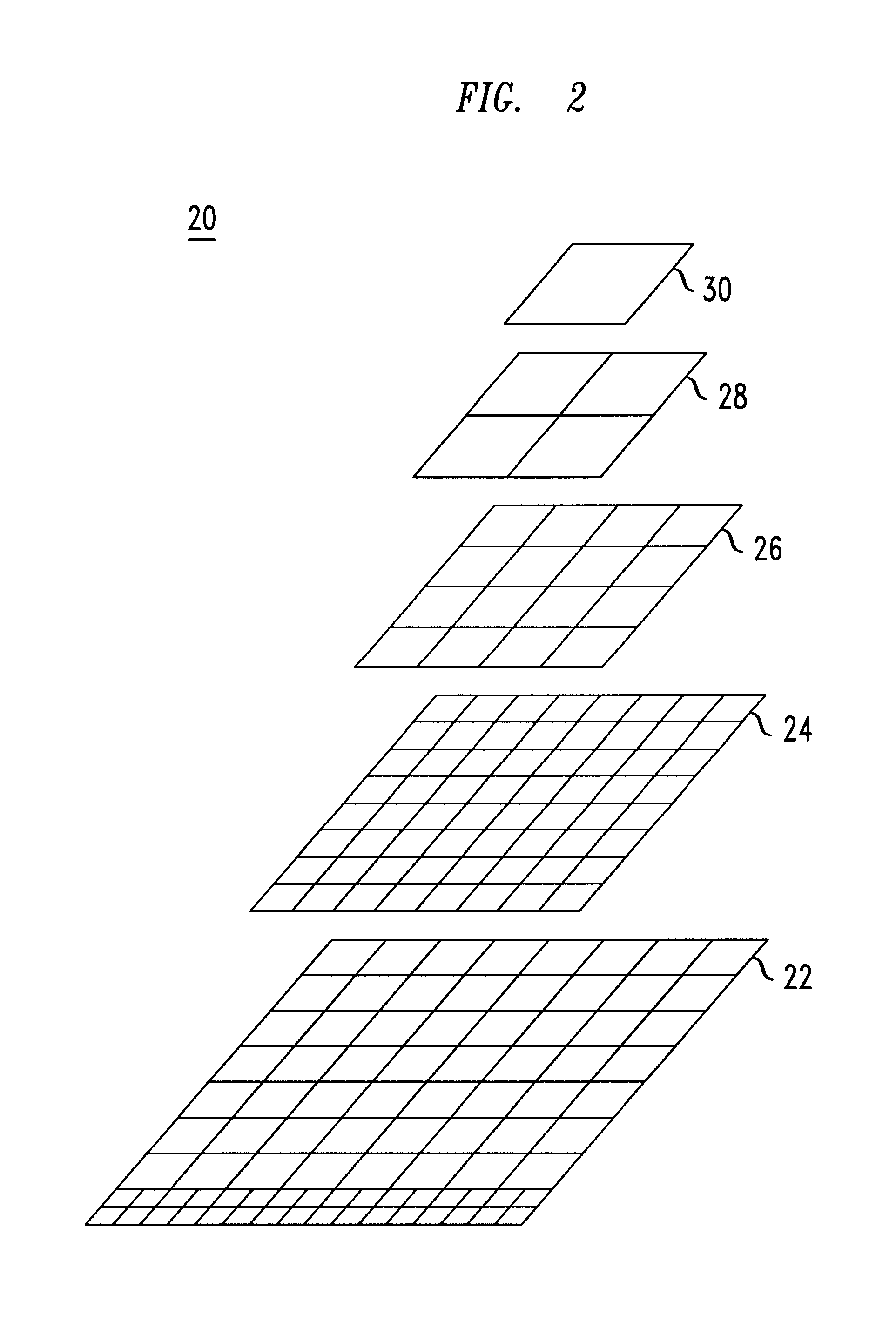
The resulting data and the details of the structure of the pruned tree are retained together for image reconstruction at a receiving display station. Thus, the pruned tree allows for coarse motion representation (fewer bits) to represent the static areas or areas with low motion activity and detailed motion representation (more bits) to represent complex motion activity. Application of a distortion parameter during pruning allows for the reduction in the image resolution of a motion field without exhibiting mosaic tiling effects of moving a group of pixels at a low image.

Problems solved by technology

In conventional serial transmission of digitized real-time video data signals, a typical communications channel has insufficient capacity to carry the large amount of data needed to accurately represent a moving video picture.
Such high data rates far exceed the practical transmission systems in use today.
Such techniques typically reduce or inhibit the transmission of pixel data that is unchanged from a predecessor frame.
However, a significant drawback of such systems is any motion is assumed to be constant over the entire block.
Thus, this relatively large size of the fixed comparison block leads to an objectionable visual distortion in the received picture when motion fields are rapid.
A further drawback is that any changes at individual pixels sites are effectively averaged with the entire block, and any complex motion that is contained within a pixel area smaller than the selected comparison block size is generally not detected.
Such small motion is therefore not included in the transmission, nor the subsequent display of the image at the receiving entity, giving attendant degradation in viewing resolution.

Method used


Image

  • Motion estimation and compensation for video compression
  • Motion estimation and compensation for video compression
  • Motion estimation and compensation for video compression

Examples


Embodiment Construction

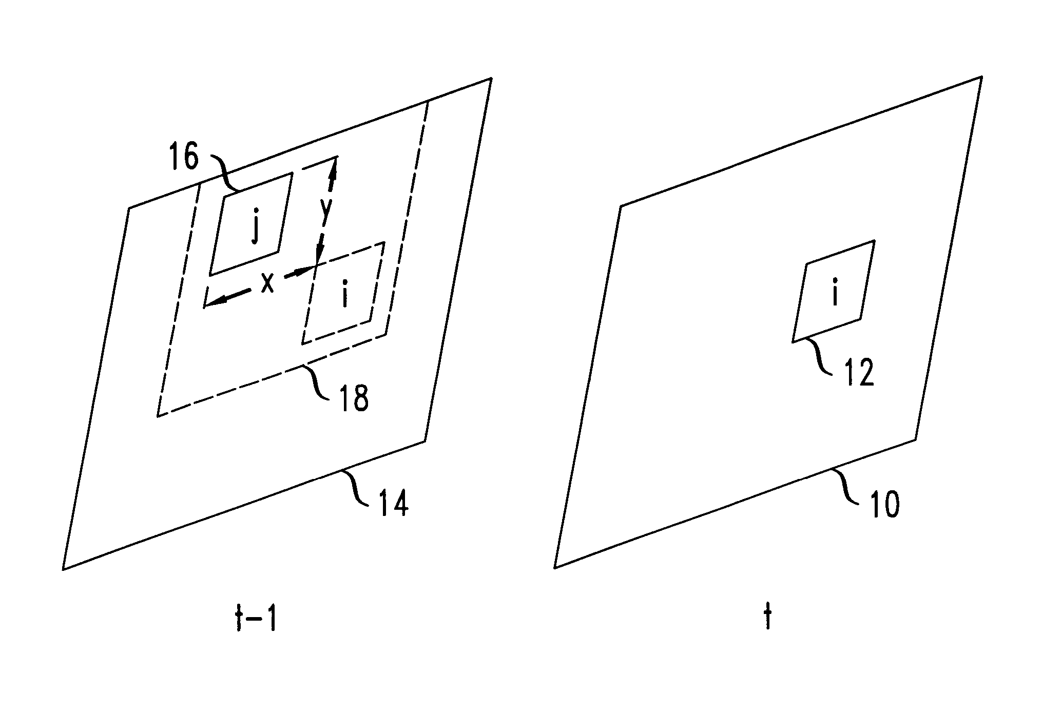
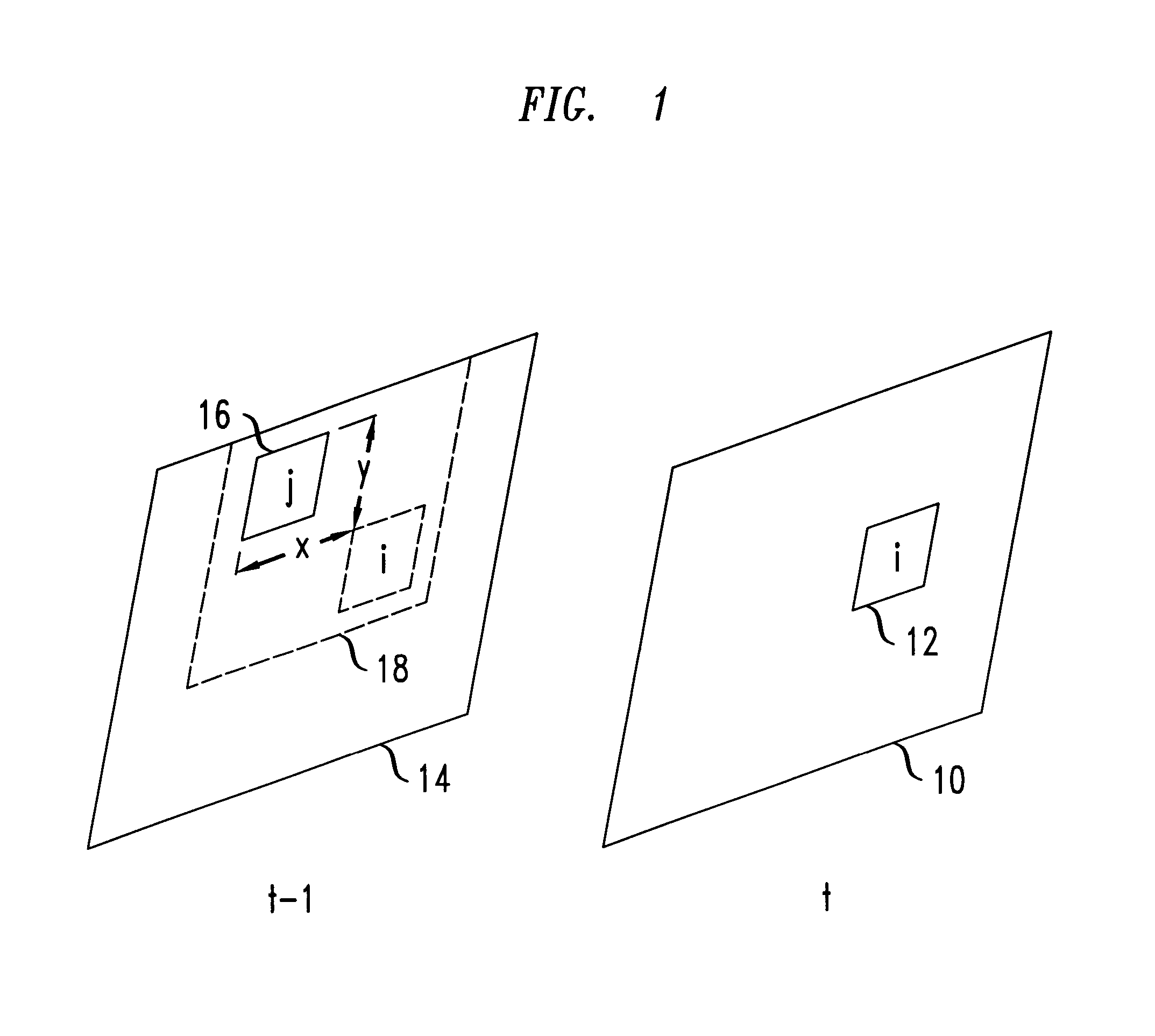
According to a preferred embodiment of the present invention, a method is disclosed for using variable-block sizes as a mask for a group of picture elements (pixels) for detecting and processing video movement, rather than the fixed-block size of conventional approaches. A video block that has no motion from a previous frame can be transmitted as a larger block than a video block that has pixel motion. A differentiation algorithm derives the largest sized data elements that can still retain the resolution of a motion event. The variable-sized elements are then stored or transmitted sequentially.

To allowing for the intermixing of such variable-sized elements, each element is preceded by a short data header, which signifies the resolution of the trailing data element. The procedure for deriving these data elements involves creating a data tree from the pixel information at the densest resolution of the video display. The data tree is then pruned to obtain the smallest data size that, ...


PUM


Abstract

An encoding method for reducing motion video data sizes using a multitude of variable-sized data blocks that are derived from spatial translation vectors and the motion field of an image. Using variable-block sizes to characterize the groups of picture elements (pixels) in an image frame allows for the inter-mixing of coarse (for static areas) and fine (for areas of complex motion) resolution data descriptions in the same descriptive data block.A comparison of motion event areas is made between successive video frames, and a motion displacement vector is calculated for each pixel location in the frame. A data tree is constructed from these pixel motion vectors and is pruned to eliminate static areas. The remaining leaves of the pruned tree are encoded differentially and applied to a lossless arithmetic encoder to provide a significantly reduced data block that still retains the highest resolution of the image.

Description

FIELD OF THE INVENTIONThis invention relates to the field of video data encoding, and more particularly to a method for the encoding a variable-motion video data signal.BACKGROUND OF THE INVENTIONIn conventional serial transmission of digitized real-time video data signals, a typical communications channel has insufficient capacity to carry the large amount of data needed to accurately represent a moving video picture. For example, in a typical video system operating at 30 frames per second, where each frame has a resolution of 720×480 picture elements (pixels) with each pixel requiring 8 descriptive data bits, a transmission channel having a capacity of 83 M bits per second would be required. Such high data rates far exceed the practical transmission systems in use today.Thus, various data reduction techniques are typically employed to reduce a real-time data transmission to more a manageable size. Such techniques typically reduce or inhibit the transmission of pixel data that is u...

Claims


Application Information

Patent Timeline
IPC IPC(8): H04N7/26
CPCH04N19/513H04N19/96H04N19/517H04N19/53H04N19/137
Inventor HAN, SOO-CHULPODILCHUK, CHRISTINE
Owner ALCATEL-LUCENT USA INC
Learn More