
Heat-absorbing filter and method for making same

a technology of heat-absorbing filters and heat-absorbing filters, which is applied in the field of heat-absorbing filters, can solve the problems of high manufacturing cost, increased manufacturing cost, and high cost of doped glass filters, and achieve the effect of low manufacturing cos

Inactive Publication Date: 2005-01-18
COMMISSARIAT A LENERGIE ATOMIQUE ET AUX ENERGIES ALTERNATIVES
View PDF12 Cites 58 Cited by
  • Summary
  • Abstract
  • Description
  • Claims
  • Application Information

AI Technical Summary

Benefits of technology

The purpose of this invention is specifically to overcome the disadvantages mentioned above, by supplying a heat filter with a low manufacturing cost and with the required properties in the visible range or in the range of the visible spectrum and in the infrared range.
In the first case, the deposition temperature is higher than in DC, of the order of 80° C., and the deposition rate is lower.
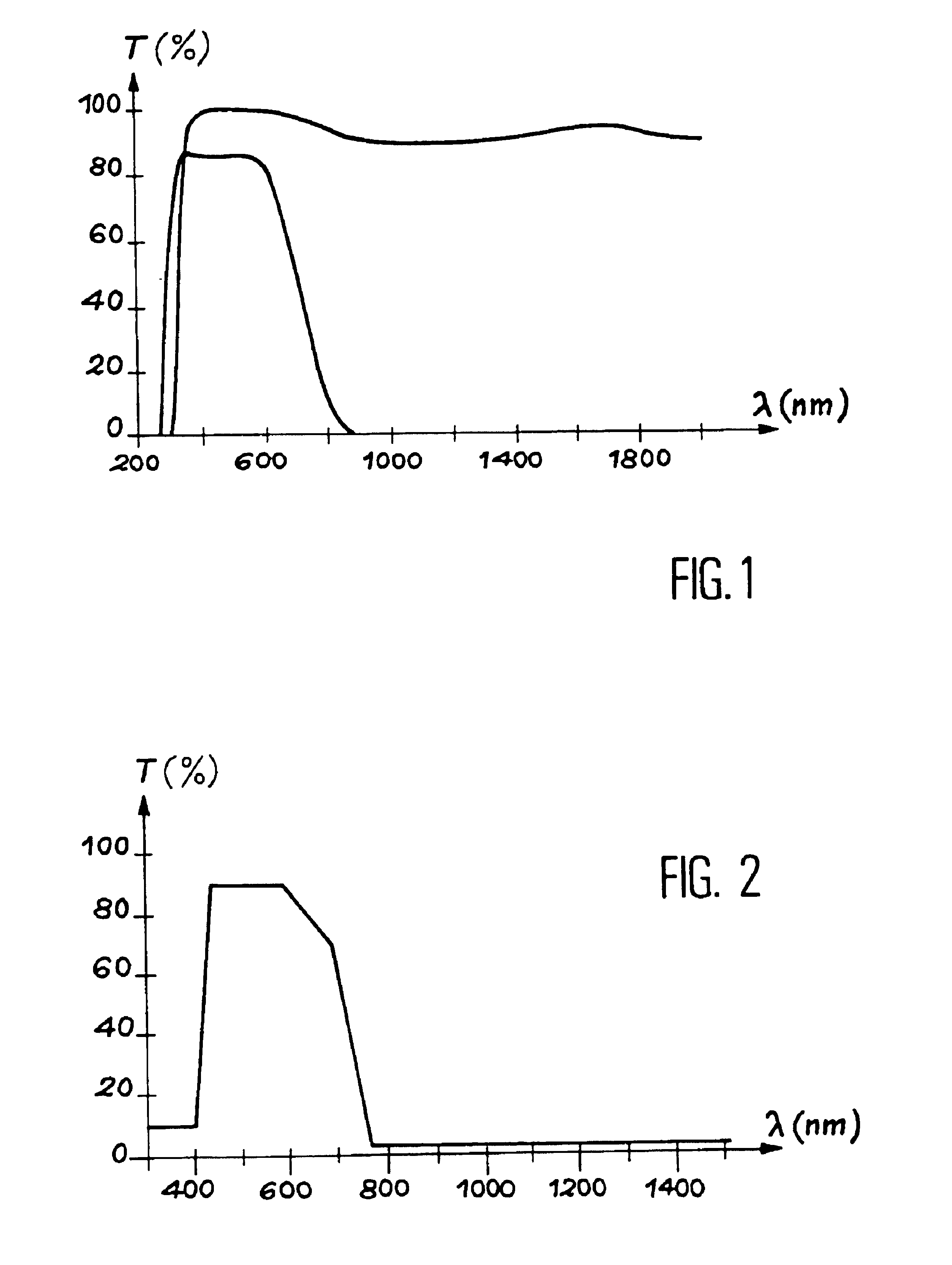
The filter in this invention makes it possible to filter the infrared radiation of illumination such as an incandescent lamp without disturbing the colour vision of the human eye.
The filter also enables good transmission in the visible spectral range. It avoids overheating of the observation area and guarantees good vision of colours and good efficiency measured as the light illumination power / electrical power.
Furthermore, its cost is much lower than the cost of prior art filters, since it uses a substrate that may be made of ordinary glass.

Problems solved by technology

Despite these good results, doped glass filters are expensive and do not operate well in a moist and warm environment.
For example, in tropical countries, it is necessary to protect this filter from humidity and ultra-violet rays by an additional layer of SiO2 which increases its manufacturing cost.

Method used


Image

  • Heat-absorbing filter and method for making same
  • Heat-absorbing filter and method for making same
  • Heat-absorbing filter and method for making same

Examples


example 2

Filter of the Present Invention wherein the Interference Filter is an SiO2 / Si3N4 Filter

The SiO2 / Si3N4 filter was deposited by IDECR (“Integrated Distributed Electron Cyclotron Resonance”) micro-wave plasma. The advantage of such a device is low temperature deposition. Indeed, it is possible to deposit a layer of SiO2 onto a polycarbonate substrate presenting good optical qualities. Furthermore, the geometrical configuration of this type of reactor allows deposition over large surfaces.

As for the TiO2 / SiO2 pair, the indices of the single layer silicon nitride and oxide were determined. Using their dispersion spectra to calculate the transmission spectrum, the following stack of 25 layers on glass (L: SiO2, H: Si3N4) was made:

6×(0.5L / H / 0.5L)+6×(0.65L / 1.3H / 0.65L)

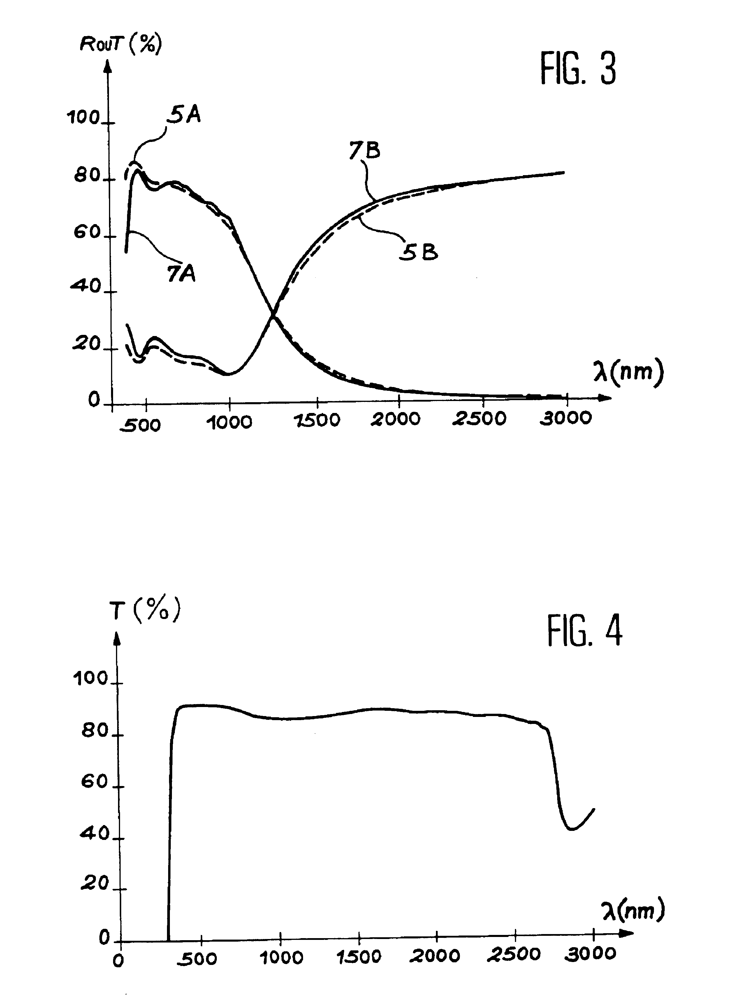
The appended FIG. 17 lists the theoretical and experimental transmission spectra of the stack made. In this figure, the axis of the x-coordinates represents the wavelength λ in nm and the axis of the y-coordinates represents pe...


PUM

PropertyMeasurementUnit
geometric thicknessesaaaaaaaaaa
thicknessaaaaaaaaaa

Abstract

The present invention relates to a heat filter and a process for manufacturing this filter.This heat filter may for example be used to filter surgical or examination lighting composed of a light source which emits energy, or radiation, in the visible and infrared ranges. It allows the light emitted by this source to be filtered so as to prevent infrared radiation from hindering the surgical team or the patient.It includes a substrate, at least one layer of an infrared reflecting material, and a coating forming an interference filter in the visible range.The invention process includes the deposition on a substrate of a layer of an infrared reflecting material and the deposition on this layer of an interference filter in the visible range.

Description

TECHNICAL FIELDThis invention relates to a heat filter and a process for manufacturing this filter.A heat filter may for example be used to filter surgical lighting composed of a light source that emits energy or radiation in the visible and infrared ranges. It must be capable of filtering light emitted by this source in order to prevent infrared radiation from hindering the operating team or the patient.This filter must block the longest wavelengths, while remaining neutral in terms of the perception of colours by the human eye within the visible range. The shortest wavelengths may also be absorbed or reflected by the filter.Apart from medical lighting, this type of filter can also be used for an examination lamp, an office lamp, an optical fibre lighting system, glazing, an optical projection system, a bulb, etc.PRIOR ARTWithin the context of an operating theatre lighting or “surgical lighting” application, this type of filter is made from a doped glass opaque to infrared radiatio...

Claims


Application Information

Patent Timeline
Patent Type & Authority Patents(United States)
IPC IPC(8): C03C17/34B32B7/02G02B5/26B32B9/00G02B5/28
CPCC03C17/3417
Inventor FIRON, MURIELMONTERRAT, ERICMONNOT, JEROME
Owner COMMISSARIAT A LENERGIE ATOMIQUE ET AUX ENERGIES ALTERNATIVES
Learn More