
Rotating aperture system

a rotating aperture and aperture technology, applied in the field of neutron radiography, can solve the problems of small leakage path, adversely affecting image interpretation, and definite leakage path, and achieve the effect of improving and extending the operating range of a “windowless” rotating aperture system

Inactive Publication Date: 2005-01-18
THE UNITED STATES AS REPRESENTED BY THE DEPARTMENT OF ENERGY
View PDF8 Cites 20 Cited by
  • Summary
  • Abstract
  • Description
  • Claims
  • Application Information

AI Technical Summary

Benefits of technology

It is an object of the present invention to provide a combination of design improvements to significantly improve and extend the operating range of a “windowless” rotating aperture system.
It is another object of the present invention to provide a combination of design improvements with a novel beam stopping technology to further improve and extend the operating range of a “windowless” rotating aperture concept.
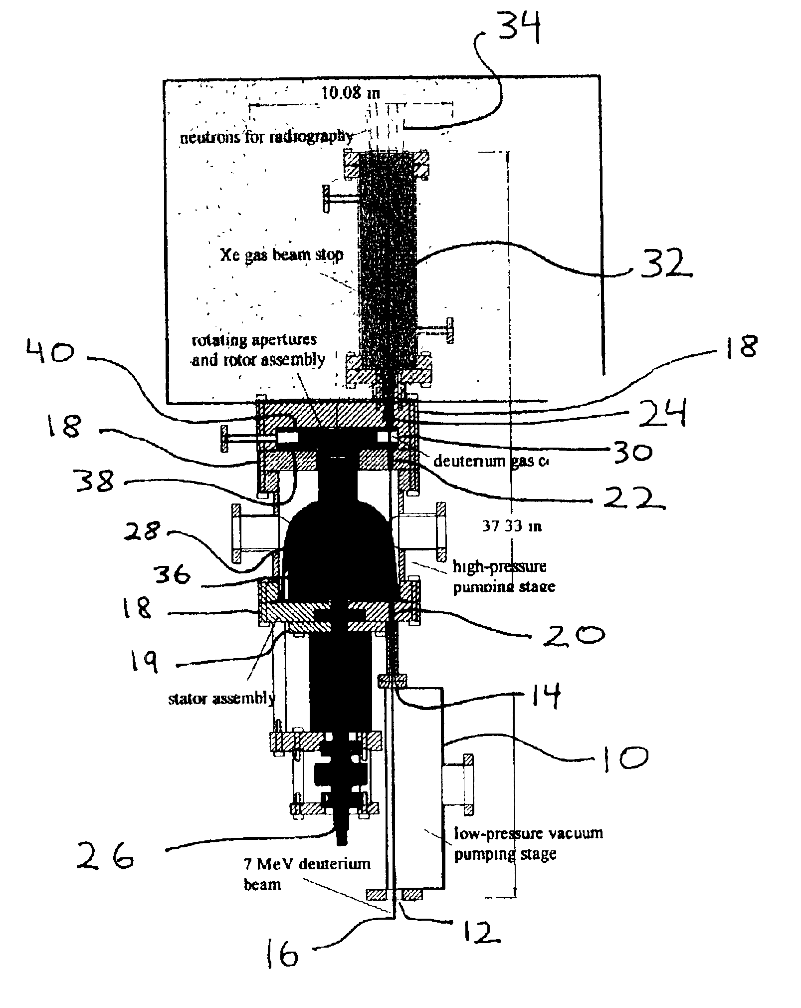
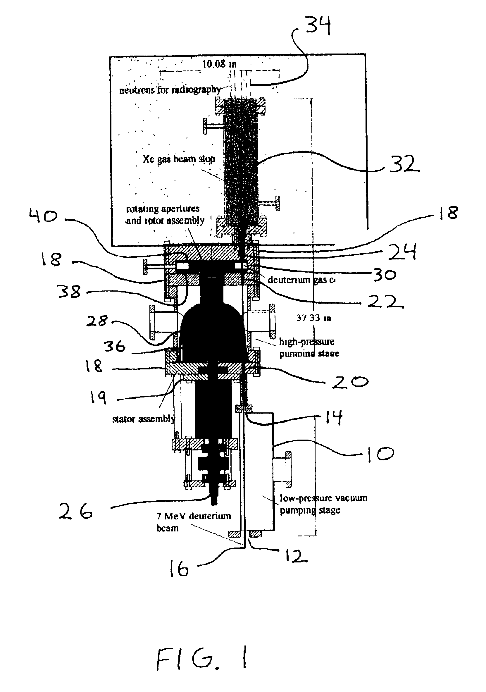
The design changes described here were initiated to improve the sealing performance of the turbulent volume gas cell aperture system by:(1) using a very rigid rotor and stator assembly to allow very close tolerances to be held at up to 4000 RPM;(2) having the rotor surface seal from the high-pressure side to the lowpressure side so the pressure gradient augments the closure seal; and(3) using special materials attached to the sliding surface of the rotor that will allow lapping of the rotor into the stator surfaces in order to achieve extremely close tolerances which result in an improved seal.
To address problems associated with gas rarefaction and de-densification due to the particle beam impinging on and depositing energy in the neutral gas in the gas cell, further design changes were initiated to improve the neutron production efficiency in the gas cell:1. A venturi tube was placed between two rotors in which the deuterium gas is passed perpendicular to the beam at a high velocity driven by a pressure drop across the venturi.2. In the rotor assemblies, baffle plates were designed to damp the sonic shock wave of gas escaping from the gas cell into the vacuum, and to provide a localized region of slightly higher pressure to impede the shock propagation.3. To decrease the deflection and vibration due to the force change that occurs when the aperture opens and closes, 2-4 additional holes that are not aligned with the rotor aperture would be used to provide a more uniform background pressure such that the transient pressure due to the beam aperture holes opening and closing is now a fraction of the total pressure.
To extend the range of operational beam powers, a high-pressure, high atomic number (Z), gas beam stop was added to the rotating aperture design concept in one embodiment This beam stop will stop deuterium beams of 50-400 μA average current in a gas rather than a solid. Such a design removes the problem of having implanted deuterium in a solid beam stop which leads to energy broadening due to off-energy neutrons in the resultant neutron beam and higher backgrounds due to scattered neutrons. It also mitigates the problem of dissipating the peak power in the beam, as the energy is deposited in a distributed fashion as the beam slows in the gas. From an imaging standpoint, the gas beam stop also minimizes attenuation of the desired neutron beam which leads to cleaner images.

Problems solved by technology

This leaves a small, but definite leakage path for gas to escape through the aperture system when it is closed.
This tends to put a large amount of material in the path of the neutron beam and would produce shadows on the object image and adversely impact interpretation of the image.

Method used


Image

  • Rotating aperture system
  • Rotating aperture system
  • Rotating aperture system

Examples


Embodiment Construction

Rotating Aperture System—Turbulent Volume Gas Cell

The improvements to the rotating aperture system described here were conceived and implemented to enhance the sealing performance, neutron production rate, longevity, radiation hardness, and reliability over the design concept originally put forth in the literature. These improvements include:

1. The sealing around the discs is improved by using a non-galling material and effectively lapping the rotor and the stator. Doing this, minimal separation is achievable between the rotor and stator which should provide maximum sealing for a closed condition. This material is a soft ceramic such as boron nitride that will conformally lap when it comes in contact with a metal surface.

2. The aperture system was designed so the rotors would seal from the higher-pressure to the lower pressure side of the aperture, thus enabling the pressure gradient to help seal the aperture. The design of the shaft on tapered bearings allowed the rotor to be preci...


PUM


Abstract

A rotating aperture system includes a low-pressure vacuum pumping stage with apertures for passage of a deuterium beam. A stator assembly includes holes for passage of the beam. The rotor assembly includes a shaft connected to a deuterium gas cell or a crossflow venturi that has a single aperture on each side that together align with holes every rotation. The rotating apertures are synchronized with the firing of the deuterium beam such that the beam fires through a clear aperture and passes into the Xe gas beam stop. Portions of the rotor are lapped into the stator to improve the sealing surfaces, to prevent rapid escape of the deuterium gas from the gas cell.

Description

BACKGROUND OF THE INVENTION1. Field of the InventionThe present invention relates to neutron radiography, and more specifically, it relates to rotating aperture systems for use in high-energy neutron imaging applications.2. Description of Related ArtConventional rotating aperture systems for use in neutron radiography use close tolerances so the rotor and stator are in close proximity but non-contacting during rotation. This leaves a small, but definite leakage path for gas to escape through the aperture system when it is closed.Stopping a 7 MeV, >50 μA average current deuterium beam on a solid target requires angled or rotating target systems that are water cooled since the power density in the beam is >120 kW. This tends to put a large amount of material in the path of the neutron beam and would produce shadows on the object image and adversely impact interpretation of the image.Stopping a deuterium beam with a solid beam stop will implant deuterium in the solid that will be...

Claims


Application Information

Patent Timeline
IPC IPC(8): G01N23/05G01N23/02G21K1/04G21K1/02H05H3/00H05H3/06
CPCG01N23/05H05H3/06G21K1/043G21K1/04
Inventor RUSNAK, BRIANHALL, JAMES M.SHEN, STEWARTWOOD, RICHARD L.
Owner THE UNITED STATES AS REPRESENTED BY THE DEPARTMENT OF ENERGY
Learn More