
Surgical clip applier having jaws adapted to guide and deform a clip

Inactive Publication Date: 2005-01-18
ETHICON ENDO SURGERY INC
View PDF30 Cites 506 Cited by
  • Summary
  • Abstract
  • Description
  • Claims
  • Application Information

AI Technical Summary

Benefits of technology

It is also an object of the invention to provide a surgical clip applier which has a pushing element which is not subject to kinking.
It is yet another object of the invention to provide a surgical clip applier which has a pushing element which does not create unsuitably high frictional forces within the outer sheath.
It is still a further object of the invention to provide a surgical clip applier which can store and apply multiple clips.
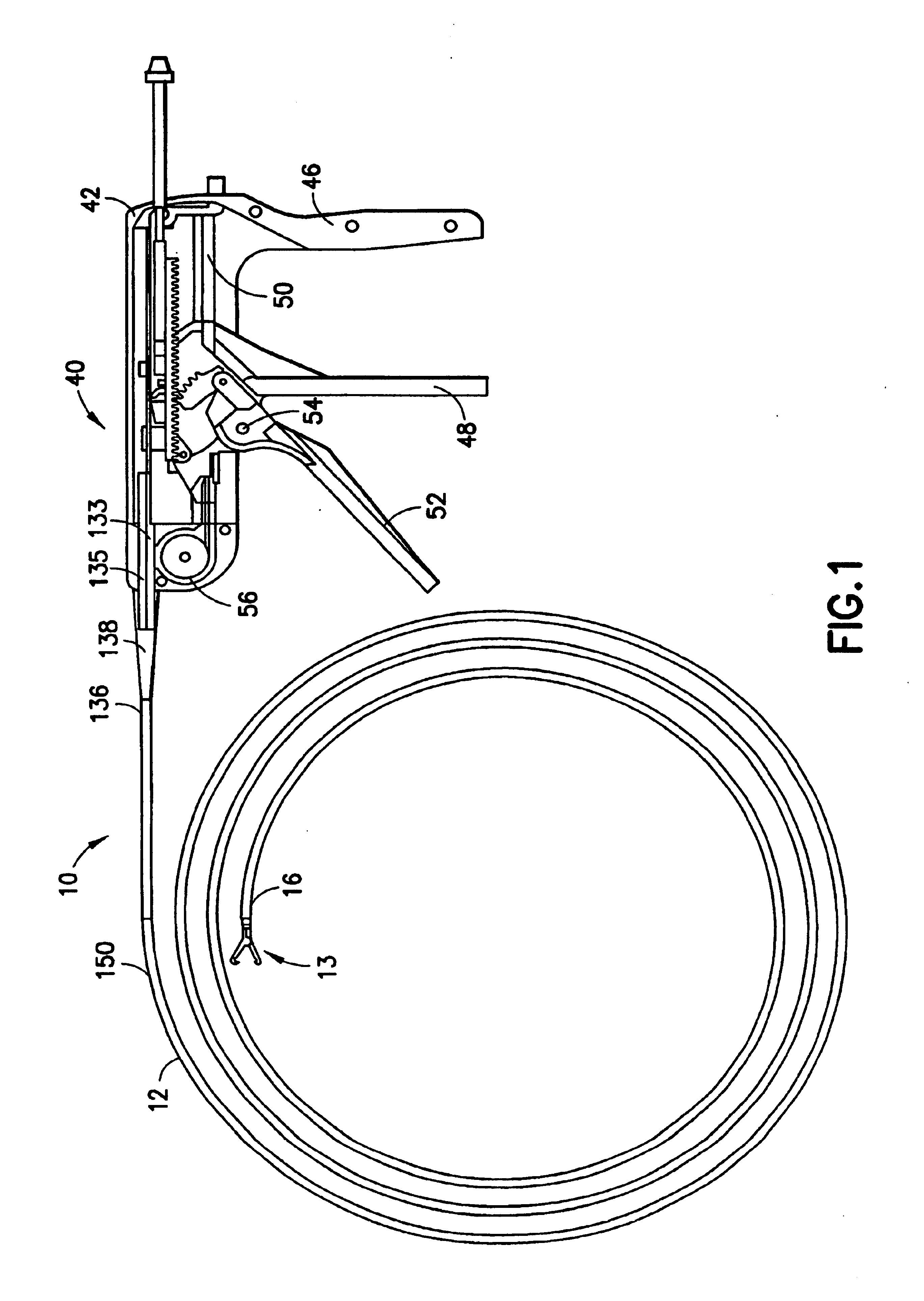
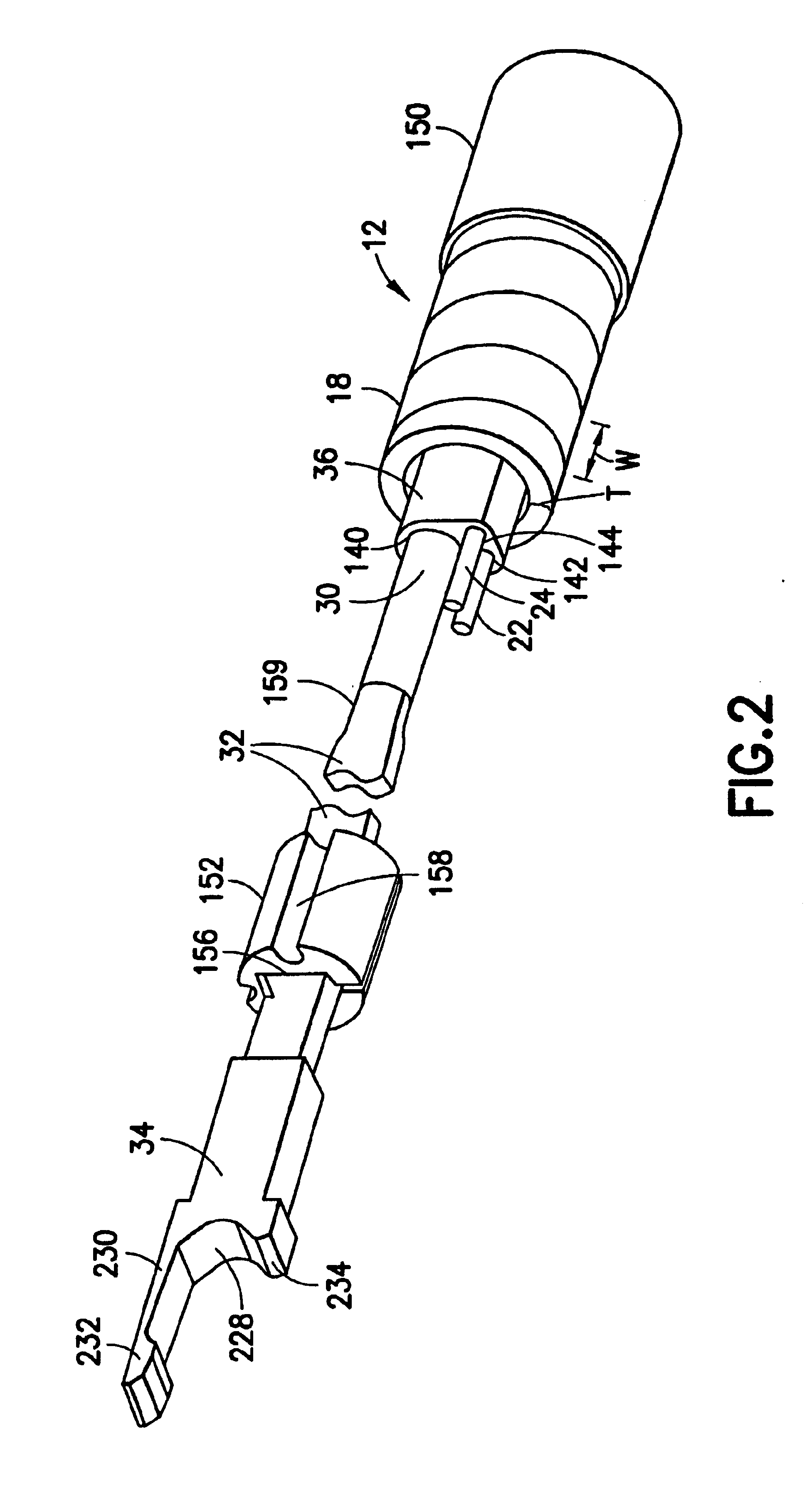
In accord with these objects, which will be discussed in detail below, a surgical clip applier is provided having a flexible, preferably flat wire wound outer tubular coil, a pair of jaws at the distal end of the tubular coil, a set of end effector wires extending through the outer tubular coil and coupled to the jaws, and a clip-advancing wire extending through the tubular coil. A lubricious, preferably extruded polymer, multilumen barrier sheath extends within the tubular coil and separates the wires from each other and the tubular coil. A clip chamber is provided in the distal end of the tubular coil and stores a plurality of linearly arranged clips. A clip pusher is provided at a distal end of the clip-advancing wire, and adapted to advance the clips in the chamber toward the jaws when the clip-advancing wire is advanced through the barrier sheath and outer tubular coil. The jaws include clamping surfaces which operate to compress tissue between the jaws when the jaws are closed, guides in which a distalmost clip rides distally and is advanced over the clamped tissue when the line of clips is advanced by the clip pusher, and a distal anvil which operates to bend a portion of the distalmost clip to enhance its retention on the clamped tissue. A proximal handle is provided for movement of the clip-advancing wire and end effector wires relative to the barrier sheath to effect (1) clamping and rotation of the jaws (relative to each other and about the longitudinal axis of the tubular coil), and (2) advancement of the clip-advancing wire to effect distal movement of a clip.

Problems solved by technology

However, it is accepted theory that the transmitted force required to advance or form a clip over tissue cannot be produced in the distalmost end of a long flexible device that is commonly constructed with a metal tubular coil, or polymer tube, such as an endoscopic device or catheter.
This type of flexible endoscopic instrument is limited in the amount of pushing force it can generate for several reasons.
Compression of a flexible control element (pushing element) tends to cause the pushing element to buckle within the outer flexible sheath of the device.
If a relatively larger diameter flexible pushing element is used such that it better resists buckling, the pushing element may impart too much stiffness to the flexing of the endoscopic instrument.
In addition, a flexible pushing element of larger diameter is subject to greater frictional forces within the outer sheath which reduces the force transmitted from the handle to the end effector.
Kinking is especially a problem in endoscopic instruments, as the endoscope and its lumen may be extended through a tortuous path.
For these reasons and others, mechanical application of a relatively large distal end pushing force and particularly clip application have been absent from the capability of flexible endoscopic tools.

Method used


Image

  • Surgical clip applier having jaws adapted to guide and deform a clip
  • Surgical clip applier having jaws adapted to guide and deform a clip
  • Surgical clip applier having jaws adapted to guide and deform a clip

Examples


example 1

In a first prototype, indicated by ‘RUN #1’, ‘RUN #2’ and ‘RUN #3’, the tubular coil 12 has an outer diameter of 0.09 inch and an inner diameter of 0.06 inch. The clip-advancing wire 30 has an outer diameter of 0.017 inch and the end effector wires 22, 24 each have an outer diameter of 0.011 inch. The proximal end of the end effector wires 22, 24 are pulled with 11 lbs of force which generally results in 5 to 10 lbs of force at the distal end of the end effector wires, depending on the degree to which the tubular coil 12 is bent (modeled by looping the tubular coil through two inch loops); i.e., frictional losses reduce the transmitted force. Moreover, it is noted that whatever force is transmitted to the distal end of the end effector wires 22, 24, only approximately one-fifth of that force is applied to the jaws, as the distance from the jaw tang 168 to the pivot 166 is relatively shorter than the length of the end of the jaw (anvil 184) to the pivot 166, approximately in a one to...

example 2

In a second prototype, indicated by ‘RUN #4’, the diameters of the tubular coil 12 and end effector wires 22, 24 are the same as Example 1. However, the diameter of the clip-advancing wire 30 is decreased to 0.015 inch. With the tubular coil 12 extending through no loops, a six pound input pushing force resulted in an output pushing force of 2.11 lbs (957 grams).

example 3

In a third prototype, indicated by ‘RUN #5’, ‘RUN #6’ and ‘RUN #7’, the diameters of the tubular coil 12 and end effector wires 22, 24 are the same as Example 1. However, the diameter of the clip-advancing wire 30 is increased to 0.02 inch. With the tubular coil 12 extending through no loops in ‘RUN #5’, an input pushing force of 8 lbs resulted in an output pushing force of 4.03 lbs (1828 grams). With the tubular coil 12 extending through one two-inch loop in ‘RUN #6’, an input pushing force of 8 lbs resulted in an output pushing force of 4.08 lbs (1851 grams). With the tubular coil extending through two-inch loops, in ‘RUN #7’, an input pushing force of 8 lbs resulted in an output pushing force of 3.54 lbs (1605.7 grams).


PUM


Abstract

A flexible clip applier includes a flat wire wound tubular coil, a pair of jaws at the end of the coil, end effector wires extending through the coil and coupled to the jaws, and a clip-advancing wire extending through the coil. A clip chamber is defined in the distal end of the coil. A clip pusher is provided at a distal end of the clip-advancing wire, and advances a clip into the jaws when the clip-advancing wire is moved distally. The jaws include channels in which a distalmost clip rides when the jaws are closed and the pusher is advanced, thereby causing the distalmost clip to be pushed over the tissue, and a distal anvil which operate to deform a portion of the clip to enhance its retention on the clamped tissue.

Description

BACKGROUND OF THE INVENTION1. Field of the InventionThis invention relates broadly to surgical devices. In particular, this invention relates to a surgical clip applier which is adapted for use through an endoscope and may be used to clamp and / or suture, ducts, vessels, and other tissues, to anchor a tissue, or to attach a foreign body to a tissue.2. State of the ArtSurgical clips are generally used to apply clamping force to ducts, vessels, and other tissues. In addition, surgical clips are particularly useful in controlling bleeding of a tissue in lieu of suturing or stapling where suturing or stapling is difficult.All of the currently available surgical multifiring clip appliers are substantially rigid devices intended to extend through a trocar port or through an incision to a surgical site requiring application of a clip. The devices have been rigid because a stiff pushing element has been required in order to exert the required pushing force to move the clip over the tissue.Ho...

Claims


Application Information

Patent Timeline
IPC IPC(8): A61B17/122A61B17/12A61B17/128A61B17/28A61B17/32A61L31/00
CPCA61B17/122A61B17/1285G01B7/10A61B17/0644Y10T24/44752A61B2017/2946A61B2017/320064A61B2017/2905
Inventor SIXTO, JR., ROBERTKORTENBACH, JUERGEN A.SMITH, KEVIN W.
Owner ETHICON ENDO SURGERY INC
Learn More