
Method and system for dynamically selecting tape drives to connect with host computers

a tape drive and host computer technology, applied in the field of data storage systems, can solve the problem of unwieldy configuration of many host computers to be connected to their respective tape drives, and achieve the effect of reducing mount times and reducing host computer configuration

Inactive Publication Date: 2005-01-11
ORACLE INT CORP
View PDF57 Cites 44 Cited by
  • Summary
  • Abstract
  • Description
  • Claims
  • Application Information

AI Technical Summary

Benefits of technology

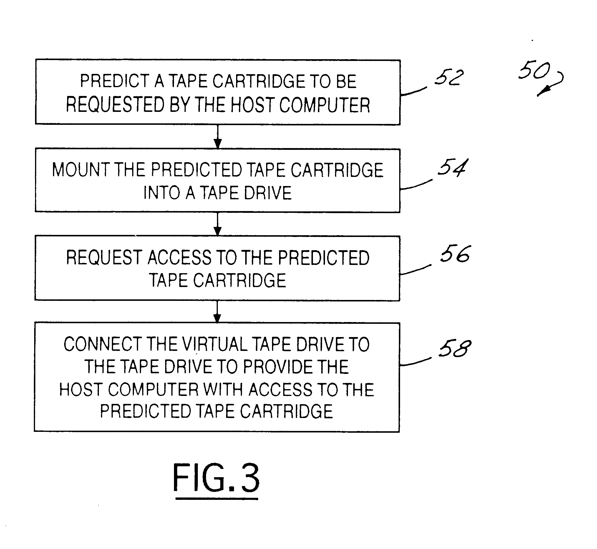
The advantages accruing to the present invention are numerous. For instance, host computer configuration is reduced and more easily managed. Adding new tape drives to the tape library will not require configuration updates to all of the attached host computers. Mount times are reduced by using the dynamically mapped scheme of the present invention because the proxy agent has all of the tape drives of the tape library to choose from. This increases the likelihood of the tape drive nearest the storage location of the desired tape cartridge being selected to mount the desired tape cartridge. Tape drive maintenance can also be performed without affecting a particular host computer because individual host computers are not tied to particular tape drives. Other potential optimizations can be performed as well. For example, scratch volumes can be pre-loaded in available tape drives so that when a mount scratch request is received, the tape drive can be made immediately available.

Problems solved by technology

A disadvantage associated with prior art data storage systems is that configuring many host computers to be connected to their respective tape drives is unwieldy when simultaneous access to many tape drives is desired.

Method used


Image

  • Method and system for dynamically selecting tape drives to connect with host computers
  • Method and system for dynamically selecting tape drives to connect with host computers
  • Method and system for dynamically selecting tape drives to connect with host computers

Examples


Embodiment Construction

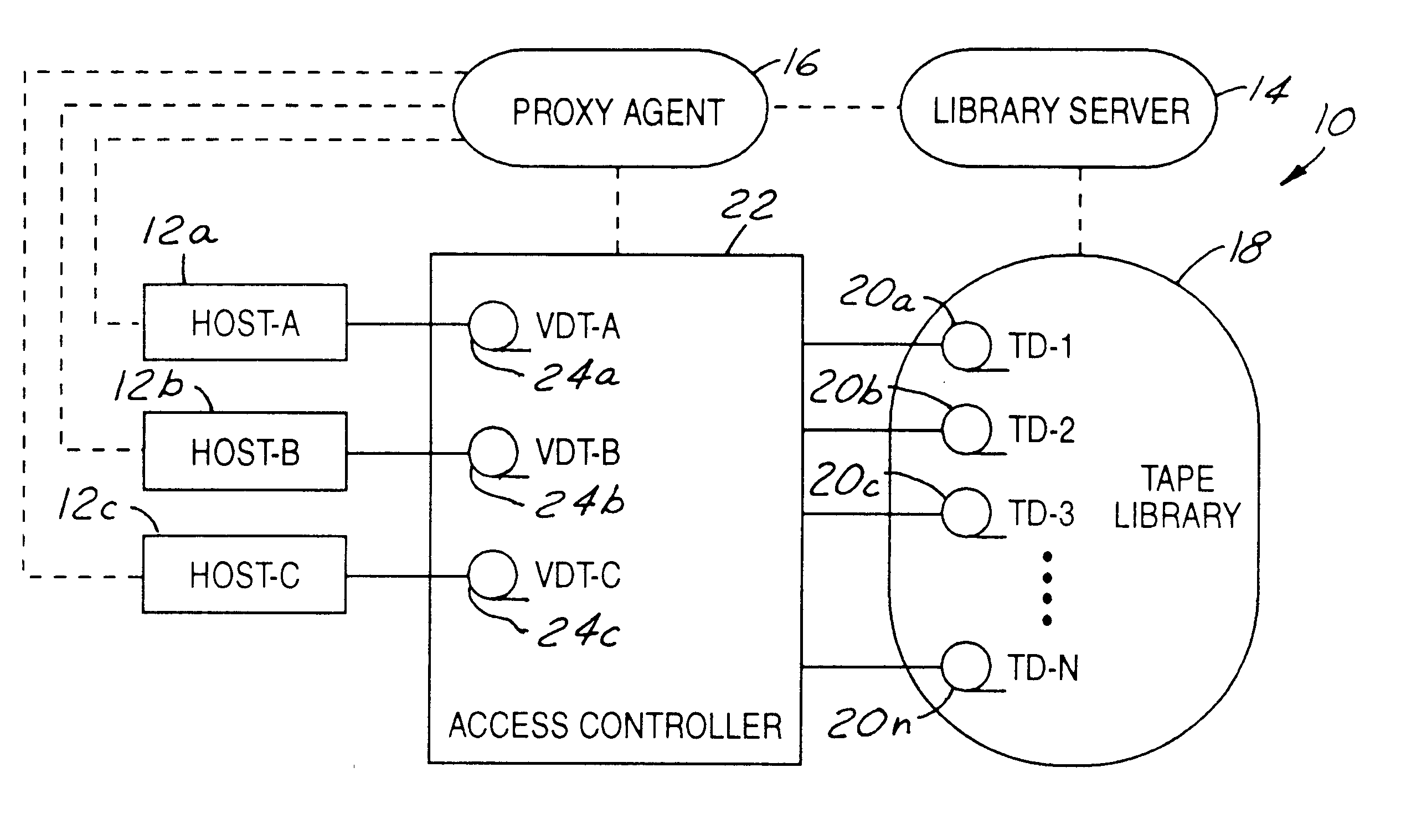
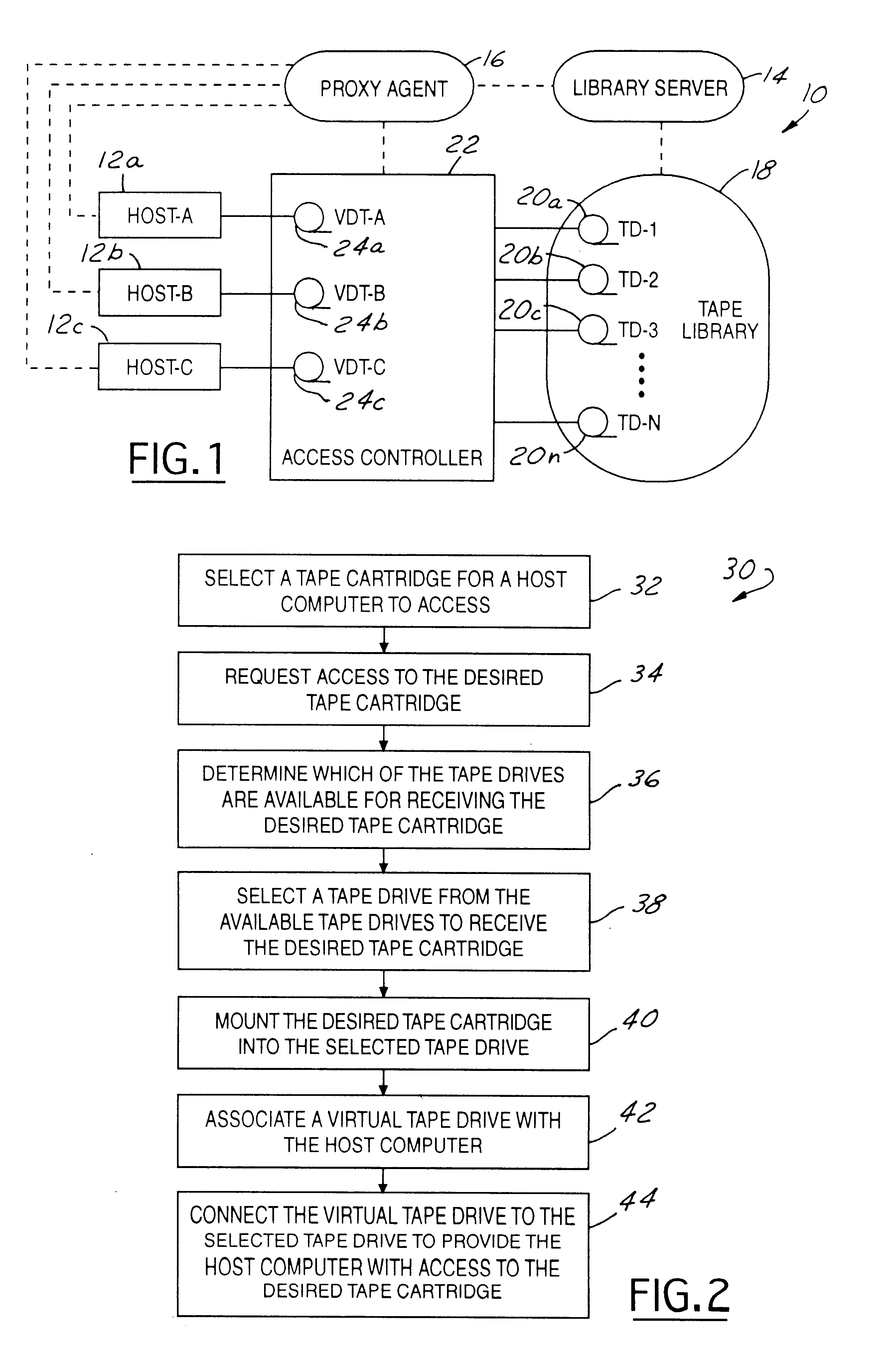
Referring now to FIG. 1, an automated tape cartridge library system 10 in accordance with the present invention is illustrated. Host computers 12a, 12b, and 12c communicate with a library server 14 via a proxy agent 16. Library server 14 governs the operation of a robot assembly within a tape library 18. Tape library 18 includes a plurality of tape cartridges. The tape cartridges have recorded data or are available to record data. Tape library 18 further includes a plurality of tape drives (TD) 20(a-n). Tape drives 20 are used to write / read data from / to the tape cartridges. An access controller 22 connects host computers 12 to tape drives 20 for the host computers to access the tape cartridges.

Library server 14 interprets signals from host computers 12 and provides appropriate signals to the robot assembly within tape library 18 to control its motion and operation. Signals from host computer 12 control the handling and storage of tape cartridges within tape library 18. In response t...


PUM


Abstract

A method and system for connecting a host to a tape drive for accessing a tape cartridge in a data storage system having a tape library provided with cartridges and tape drives includes the host requesting a desired cartridge to access. In response to the request, a proxy agent queries the library to determine which of the tape drives are available to receive the desired cartridge. The proxy agent then selects a tape drive from the available tape drives to receive the desired cartridge. The desired cartridge is then mounted into the selected tape drive. An access controller then connects a virtual tape drive associated with the host to the selected tape drive to provide the host with access to the desired cartridge. The selected tape drive may be selected as a function of its location with respect to the storage location of the desired cartridge. While the host computer is accessing the desired cartridge, the access controller may simultaneously connect another virtual tape drive associated with a second host to another tape drive to provide the second host with access to a different cartridge.

Description

TECHNICAL FIELDThe present invention relates generally to data storage systems and, more particularly, to a method and system for dynamically selecting tape drives to connect with host computers.BACKGROUND ARTA popular device for handling large amounts of information in a data storage system is the automated cartridge library. Automated cartridge libraries store and manage large numbers of tape cassettes containing magnetic tape on which is recorded data. Typically an automated cartridge library comprises a tape library having arrays of uniquely identified cells, each cell being formed to contain a single tape cartridge. A robot assembly is operable within the tape library to locate a particular cell, retrieve a tape cartridge from the particular cell, convey the tape cartridge to a tape drive, and insert the tape cartridge into the tape drive. The tape drive then reads or writes data to the magnetic tape of the tape cartridge. In this way, a large number of tape cartridges are auto...

Claims


Application Information

Patent Timeline
IPC IPC(8): G06F3/06G11B31/00G11B27/00G11B15/68G11B27/10
CPCG06F3/0626G06F3/0632G06F3/0686G11B27/002G11B31/00G11B15/689G11B2220/90G11B2220/41
Inventor KUIK, TIMOTHY JOHNWEBER, RENAE M.BAKKE, MARK A.
Owner ORACLE INT CORP
Learn More