Adapter for a light source

Inactive Publication Date: 2005-01-11
LED IBOND IPR APS
View PDF10 Cites 12 Cited by
  • Summary
  • Abstract
  • Description
  • Claims
  • Application Information

AI Technical Summary

Benefits of technology

The object of the invention is to provide an easy way of mounting and servicing light emitters mounted in one plane, to reduce the need for wiring and to facilitate the making of thin displays.

Problems solved by technology

The number of wires may therefore be great, implying a relatively high production price and difficulties in making thin displays.
With this type of displays, a large number of light emitters are to be used, causing the same disadvantages as mentioned above.

Method used


Image

  • Adapter for a light source
  • Adapter for a light source
  • Adapter for a light source

Examples


fifth embodiment

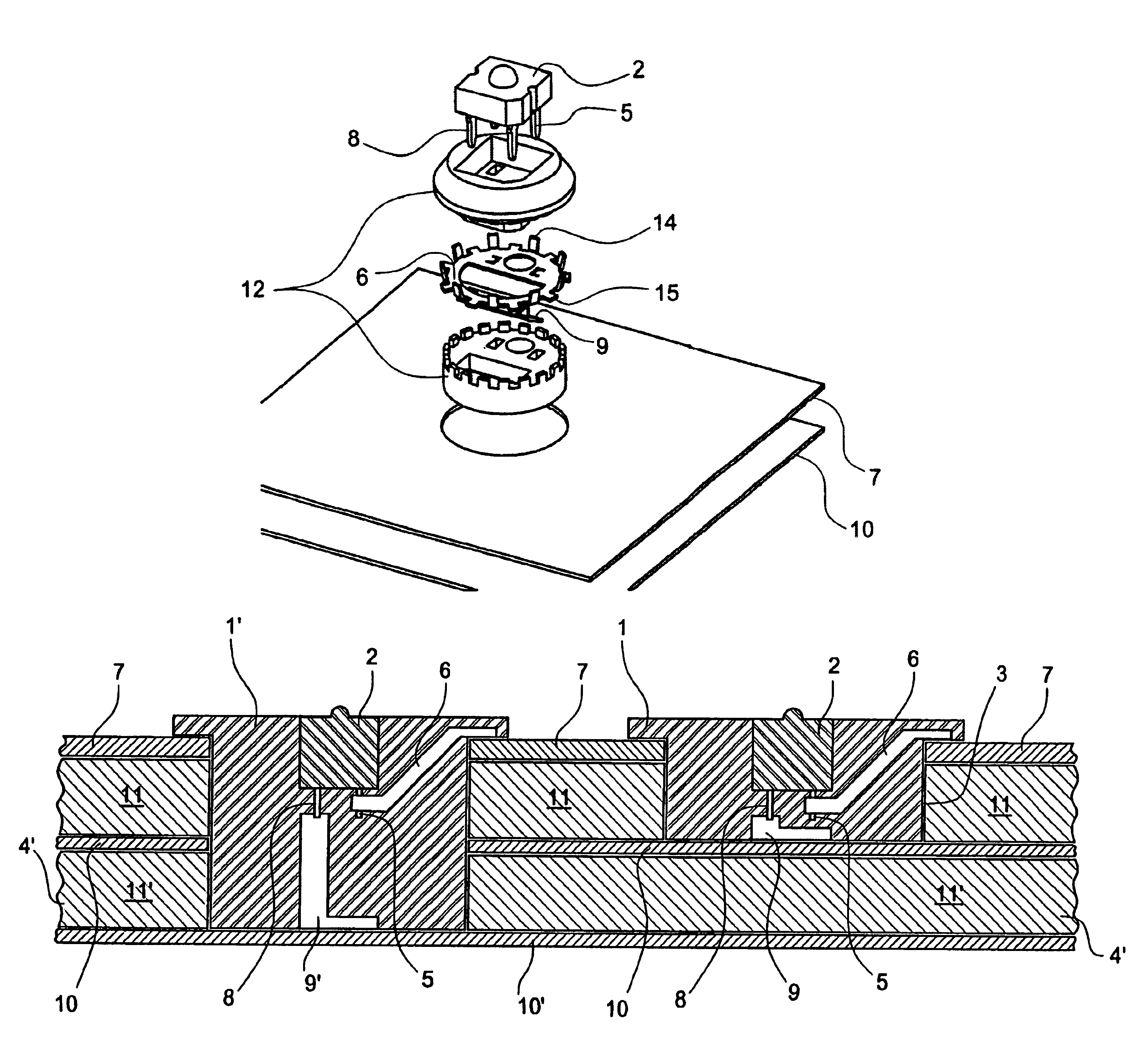
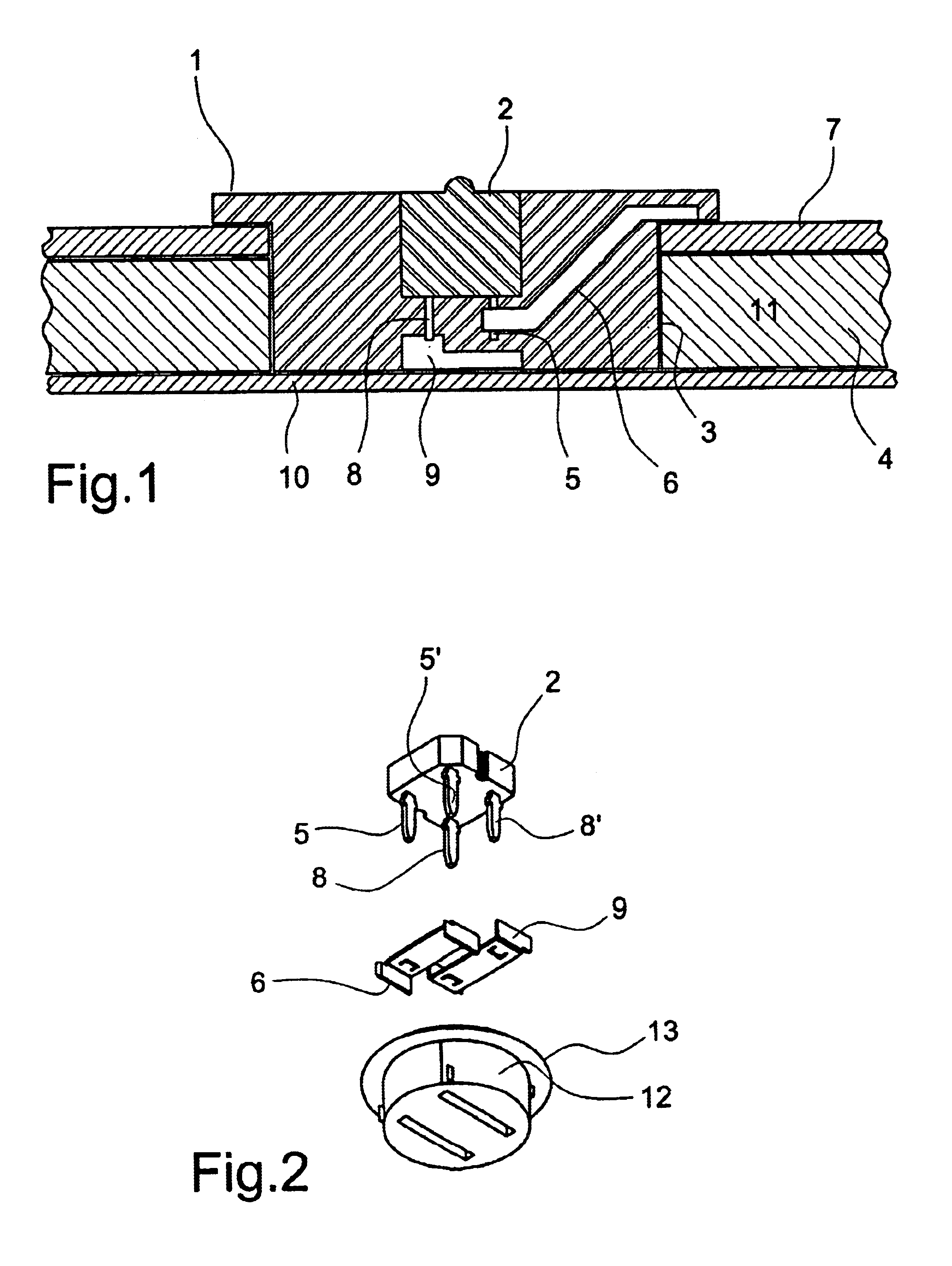
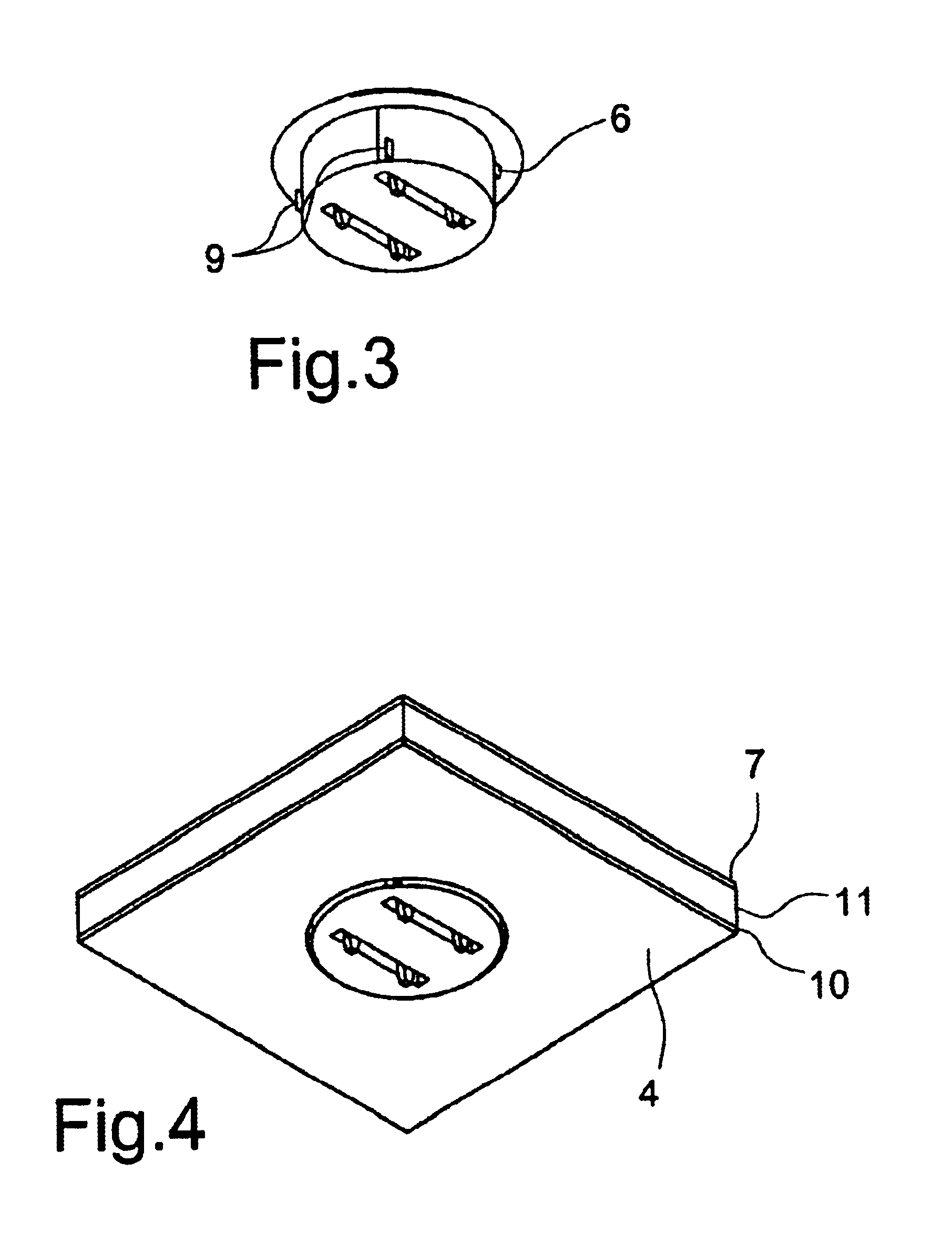
the adapter shown in FIGS. 14-16 is described in detail below.

The bearing principle of the construction is that the electric connections for a large number of light diodes go through two aluminum layers at front and rear sides, respectively, of an aluminum / PVC laminate or sandwich board, which is henceforth called the composite, and that this composite is the main component in a flat display structure which can be tailor made, put up and operated reliably everywhere, inter alia on building fronts outside.

With this embodiment, the following advantages are achieved:The adapter may be mounted and fixed in the composite in a simple and secure way.Separation with the purpose of recycling the raw materials of the device is possible.The aluminum sheets at the front and rear sides of the composite function as conductors for electrical currents for the cathode and anode pins, respectively. The front side also functions as a cooling panel for the power losses in the light diodes.In connection...


PUM


Abstract

An adapter for at least one light emitter for mounting in a aperture in a sandwich board comprising a core of electrically insulating material, the core being provided with a layer of electrically conducting material at each side of the core, where the aperture is continuing at least partly through the sandwich board, the adapter comprising one or more first pins that are adapted for establishing electrically conducting connection with one of the layers when mounting the adapter in the aperture, and at least one second pin adapted for establishing electrically conducting connection with the other layer when mounting the adapter in the aperture.

Description

This application claims the benefit of Danish Application No. 2001 01213 filed Aug. 13, 2001 and Danish Application No. PA 2001 01720 filed Nov. 19, 2001.BACKGROUND OF THE INVENTIONThe present invention concerns an adapter for a light emitter for mounting in a aperture in a sandwich board and use of such adapter for forming a desired image.It is common to make light displays where a number of light emitters are mounted on the display. The light emitters are disposed so that they form the shape or the text to be shown by the display. The light emitters are supplied with electric voltage with a number of wires as each single light emitter has to be individually connected with a power supply. The number of wires may therefore be great, implying a relatively high production price and difficulties in making thin displays.Alternatively, the displays are made with light conductors connected with one or more external light emitters. With this type of displays, a large number of light emitte...

Claims


Application Information

Patent Timeline
IPC IPC(8): H01R4/24H01R33/00H01R24/04H01R24/00H01R33/94F21V19/00F21V21/002H05K3/30H05K1/18H01R24/58
CPCH01R33/94H01R4/2404F21V19/001F21V21/002H05K3/301H05K1/184
Inventor S.O SLASHED.RENSEN, NICOLAJHARRIT, THOMAS
Owner LED IBOND IPR APS
Why Eureka
Try Eureka