
Modular, pneumatically operated control valve

a control valve and module technology, applied in the direction of valve details, valve arrangement, spindle sealing, etc., can solve the problems of large actuating drive large actuating drive, etc., to minimize wear on elastic spindle seal, reduce wear on seal, and reduce wear

Inactive Publication Date: 2005-01-11
JAHN PETER
View PDF5 Cites 10 Cited by
  • Summary
  • Abstract
  • Description
  • Claims
  • Application Information

AI Technical Summary

Benefits of technology

"The invention is a valve with a pneumatic or hydraulic actuator that has a flow passage through the valve housing. The valve has a closing mechanism consisting of a valve spindle and a separate freely movable closing body. The valve spindle is guided movably in a cavity and has a fluid pressure line connected to it. The closing mechanism is positioned above the flow passage and has a centering plate with a pressure relief space and seals that separate it from the flow passage and the lower cavity. The valve is designed to withstand high differential pressures and has a short closing time. The valve is modularly assembled and has built-in parts that allow force transmission between different spaces, which is achieved through the valve spindle. The valve is suitable for use with compressed gases such as hydrogen."

Problems solved by technology

If the valve is required to assume a defined safety (i.e., “fail safe”) position in the event of the failure of control energy, the valve actuators and consequently the controllable valve become disproportionably larger.
For this reason, in particular, known actuated control valves are too large, and therefore unsuitable, for use in miniaturized and automated test installations.
This leads, as a rule, to very large actuating drives.
The disadvantage of such a design is that, over the course of a comparatively large number of actuations of the valve (>10,000 switching cycles), the diaphragm may become leaky or may tear.
The product then leaks from the flow passage or valve process space into the interspace between the valve spindle and valve body and ultimately even possibly into the surroundings.
Valves have to execute long travels for a complete closing movement between the end positions OPEN and SHUT, and therefore the construction of a spindle seal, particularly where prevailing high process pressures are concerned, becomes complicated and expensive.
If, however, this valve is used for a task in which the full actuating range (actuating travel) is covered constantly, so that the valve is constantly moved between the end positions OPEN and SHUT, pronounced abrasion occurs at the spindle seal, so that a design-based adjustment possibility is quickly used up, the spindle seal is no longer leak-tight and a leakage occurs.
The result of this is that such designs of spindle seals are not suitable in valves for high process pressures, such as, for example, 300 bar hydrogen.
The alternating stress generates high material tensions in the material of the diaphragms or bellows, so that, in the case of miniaturized valves, material fatigue and therefore failure of the metal seal components quickly occur.
The design-based increase in size of the diaphragm or bellows requires an increase in the effort for the valve-spindle movement, so that the construction size of the actuating drive and therefore of the controllable valve increases.
Valves of this type are not suitable for compact miniaturized test installations.
A further problem is the leak-tightness of the valve seat.
If high switching frequency leads to increased wear in the region of the spindle seal, the original low position tolerance is increased appreciably and the spindle tip can no longer move into the exactly fitting sealing seat first formed and close the valve passage in a leak-tight manner.
The valve types thus produced have only a short service life in the case of a high differential pressure applied by the gas and in the case of frequent rapid switching cycles.
The least possible axial variation in the region of the valve-spindle guide and the spindle seal changes the position of the concentric linear seal and results in leakages in the flow passage.
Investigations on various commercially available valves confirm that, in the case of a hydrogen load under a pressure of up to 300 bar, with high pressure differences between the two sides of the valve, i.e., between the inlet and outlet, there was initially high leak-tightness.
On account of the rapid and high switching frequency, the valves showed first leakages after fewer than 10,000 load cycles.
Those valves which were able to remain leak-tight even after a larger number of switching cycles had substantially larger drive and large valve forms of construction, and therefore the use of such valves in miniaturized installations would be too complicated and too cost-intensive.
In addition, the switching time required for an OPEN / SHUT movement of the valve should be extremely short.

Method used


Image

  • Modular, pneumatically operated control valve
  • Modular, pneumatically operated control valve
  • Modular, pneumatically operated control valve

Examples


example 1

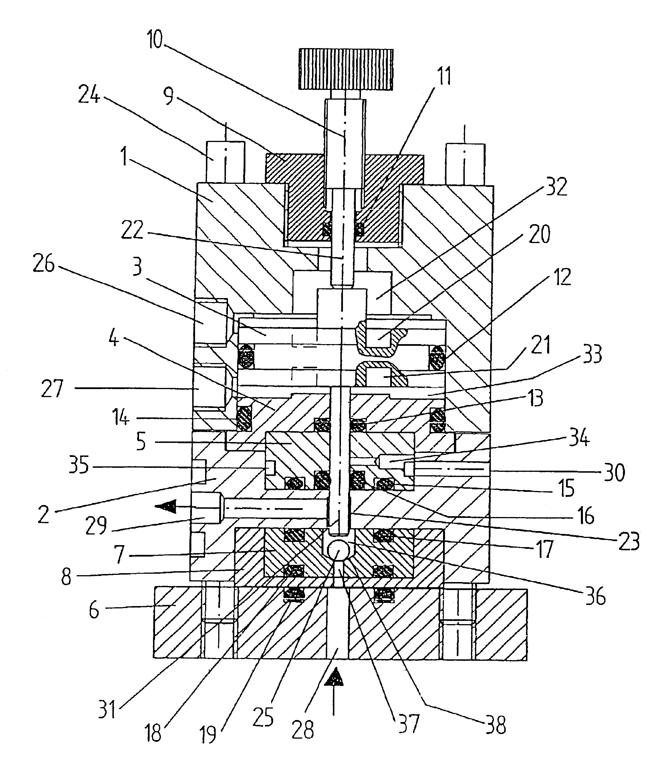
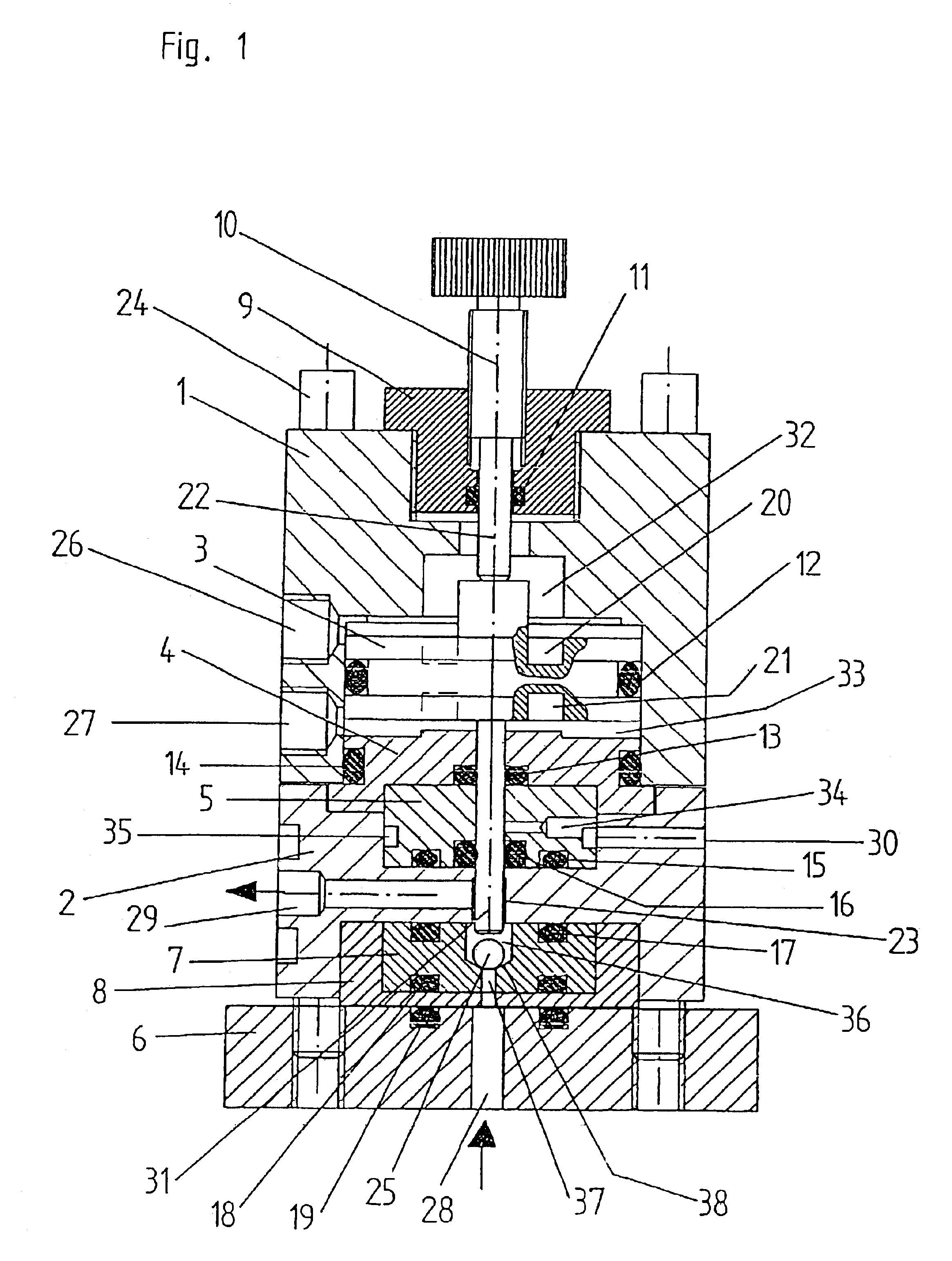
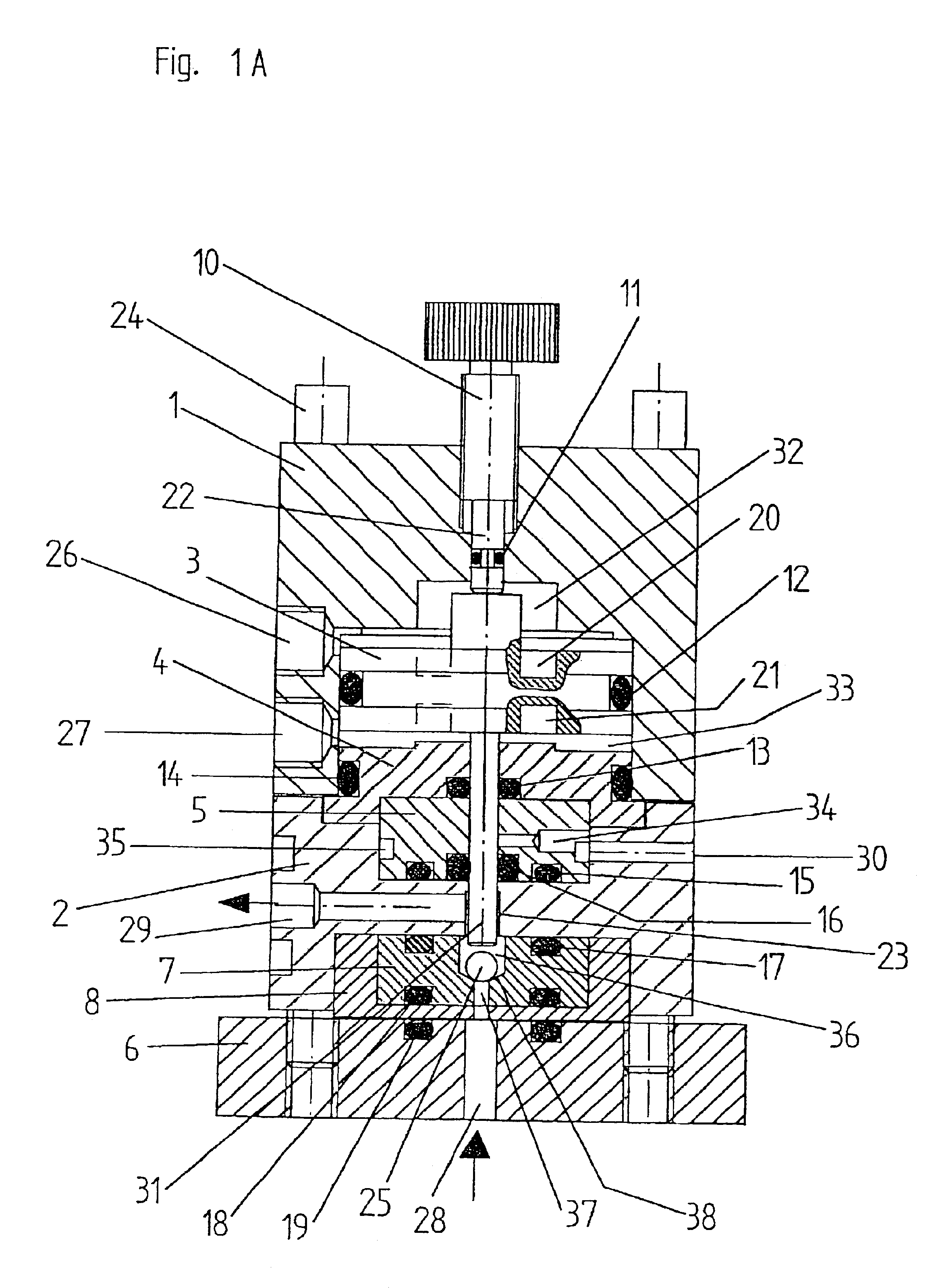
[0132]FIG. 1 shows a sectional illustration of a valve with an integrated pneumatic adjusting drive. The valve has three main plates, the head plate 1, the housing plate 2 and the base-plate 6. All the plates are held together, for example, by means of four screws 24, or by bolts, etc.

[0133]The head plate 1 has, inside it, a stepped bore. The bore forms the cavity 32, 33, referred to below as the pneumatic space. The pneumatic space 32, 33 of the head plate 1 provides space for receiving a piston 3 with a valve spindle 31 attached on one side. The piston 3 has, on its circumference, a groove for receiving the elastic piston seal 12. The piston seal 12 and the piston 3 divides the pneumatic space 32, 33 into a lower cavity 33 and an upper cavity 32 (also referred to as the lower and the upper pneumatic space).

[0134]The lower pneumatic space 33 ends with the centering closing plate 4 and is sealed with an associated outer seal 14 to the inner bore of the head plate 1. The piston-spind...

example 2

[0143]FIGS. 2 to 2c illustrate various embodiments of the valve-sealing seat 7 in a valve according to FIG. 1

[0144]FIG. 2 shows the angle α of the conical sealing area 38, the closing body 25 and part of the valve spindle 31

[0145]FIG. 2a shows a version with a conical closing body 25′ and with a centering pin on the valve spindle 31′

[0146]FIG. 2b shows a plate-shaped closing body 25′″ with a centering pin on the valve spindle 31

[0147]FIG. 2c shows a pointed conical closing body 25″ which in the closed state projects predominantly into the feed duct 37 (bore).

example 3

[0148]FIG. 3 shows an alternative valve seat 7′ for a valve according to FIG. 1, with an elastic inner valve-seat seal 42. The freely movable closing body 25″ is in the form of a rotationally symmetrical cylinder stepped on one side and having an attached guide cone. The receiving bore for the closing body 25″ is part of the valve seat 7. If an inner elastic seal is used in the valve seat 7′, the closing body and the valve seat may be made from the same material.


PUM


Abstract

A modular, actuated valve controlled by means of pressure fluids comprising a head plate mounted on a housing plate mounted on a base plate, held together by screws, having a piston with attached valve spindle and a pressure relief space provided between the flow passage 28, 29 and the piston.

Description

BACKGROUND OF THE INVENTION[0002]Actuated miniaturized process valves for high pressures, for example, pressures higher than 300 bar, are usually constructed of a valve body, an electric or pneumatic actuator and a connecting mounting unit. This makes it necessary for the valves to have spatially large forms of construction. If the valve is required to assume a defined safety (i.e., “fail safe”) position in the event of the failure of control energy, the valve actuators and consequently the controllable valve become disproportionably larger. For automated and miniaturized test installations, actuated gas-tight valves with spatial dimensions smaller than 50 ml are required, so that a compact installation set-up is possible. For this reason, in particular, known actuated control valves are too large, and therefore unsuitable, for use in miniaturized and automated test installations. All known valves are very similar in terms of construction.[0003]The construction of known valves varie...

Claims


Application Information

Patent Timeline
Patent Type & Authority Patents(United States)
IPC IPC(8): F16K31/122F16K41/00F16K41/02F16K51/00
CPCF16K31/122F16K41/02Y10S137/901
Inventor JAHN, PETERKRAUTKRAMER, RAINERFERVER, EMIL
Owner JAHN PETER
Learn More