Valve actuator

Inactive Publication Date: 2005-01-11
CANRIG DRILLING TECH
View PDF14 Cites 27 Cited by
  • Summary
  • Abstract
  • Description
  • Claims
  • Application Information

AI Technical Summary

Benefits of technology

In accordance with the present invention, a valve actuator is provided that eliminates or reduces disadvantages or problems associated with prior valve actuators. The valve actuator of the present invention includes a largely symmetrical dual crank design in which a pair of racks drive each pinion. Each rack is part of bearing assembly, the elements of which are shielded by a cooperating bearing housing and bearing retainer. The pinions and racks are themselves shielded by a shielded plate that protects the racks and pinions from foreign objects and prevents the pinion from being thrown from the valve actuator. The two bearing assemblies of the valve actuator are coupled to one another through a hydraulic or pneumatic cylinder, which when actuated moves the racks relative to one another to rotate the pinion to open or close the valve that is being actuated.
The present invention is advantageous because of the placement and operations of the racks and pinions. Because the pinions are located on opposite sides of the valve actuator, driving the pinions by applying force to the pinions from opposite sides of the valve to be actuated allows for balanced couple actuation and does not introduce substantial side loading effects on the pinion. The valve actuator is also advantageous in that it is able to rotate in a drill string with the valve itself, and therefore need not include rotary seals in an attempt to accommodate rotation of the valve relative to rotation of the valve actuator. The valve actuator of the present invention is also advantageous in that many of the most critical components of the valve actuator are shielded. The racks and pinions are shielded by a pinion retaining shield, and each of the bearing assemblies includes a bearing housing and bearing retainer that cooperate to enclose the bearings of the bearing assemblies. The valve actuator of the present invention also accommodates the manual activation of the valve. A key can be inserted in the hex hole of the pinion. Rotation of the pinion causes the racks to move relative to the pinion, opening or closing the valve.

Problems solved by technology

Because the blowout prevention valves in a top drive drilling environment may be rotating and moving along a vertical line up and down the derrick, actuation of these valves is difficult simply because the valves are not stationary.
In the case of non-stationary valves, it is difficult to supply hydraulic or electric power to the valve actuator, especially when the valve is both rotating and moving in a vertical direction.
These designs, however, introduce excessive mechanical wear in the actuator, and are often unreliable as a result.
In the case of the rotational seal, the quality of the rotational seals is often poor because of the rotation and the speed of the rotation.
The introduction of dirty or contaminated air in the vicinity of the drilling rig can introduce contaminates into the actuator, thereby causing the internal mechanisms of the actuator to deteriorate.
In cold climates the introduction of air into the actuator can lead to condensation in the actuator.
In addition, the inclusion of an actuator that is controlled by air pressure is often an inefficient design choice when many, if not all, of the others devices on the drilling rigs are driven by hydraulic power.
Hydraulic actuators have similar difficulties, especially in climates other than cold climates.
Dual crank valves have greater torque capability as compared with single crank valves, which may have limited torque capability because of the presence of only a single crank and the space constraints of the valve itself.
If the ball of the ball valve is not fully closed, fluid that seeps through the partially closed valve may harm the components of the valve or actuator.
If the ball of the ball valve is not fully opened, fluid is not allowed to pass through a fully opened passageway, thereby potentially restricting fluid flow.
The problem of ball rotation is exacerbated because valve actuators use start and stop points for mechanical actuator movement that are dependent on mechanical start and stop points on the valve itself.
As the valve becomes worn, these stop and start limiters may become worn or may be out of alignment, causing the ball of the valve to be rotated imprecisely.

Method used


Image

  • Valve actuator
  • Valve actuator
  • Valve actuator

Examples


Embodiment Construction

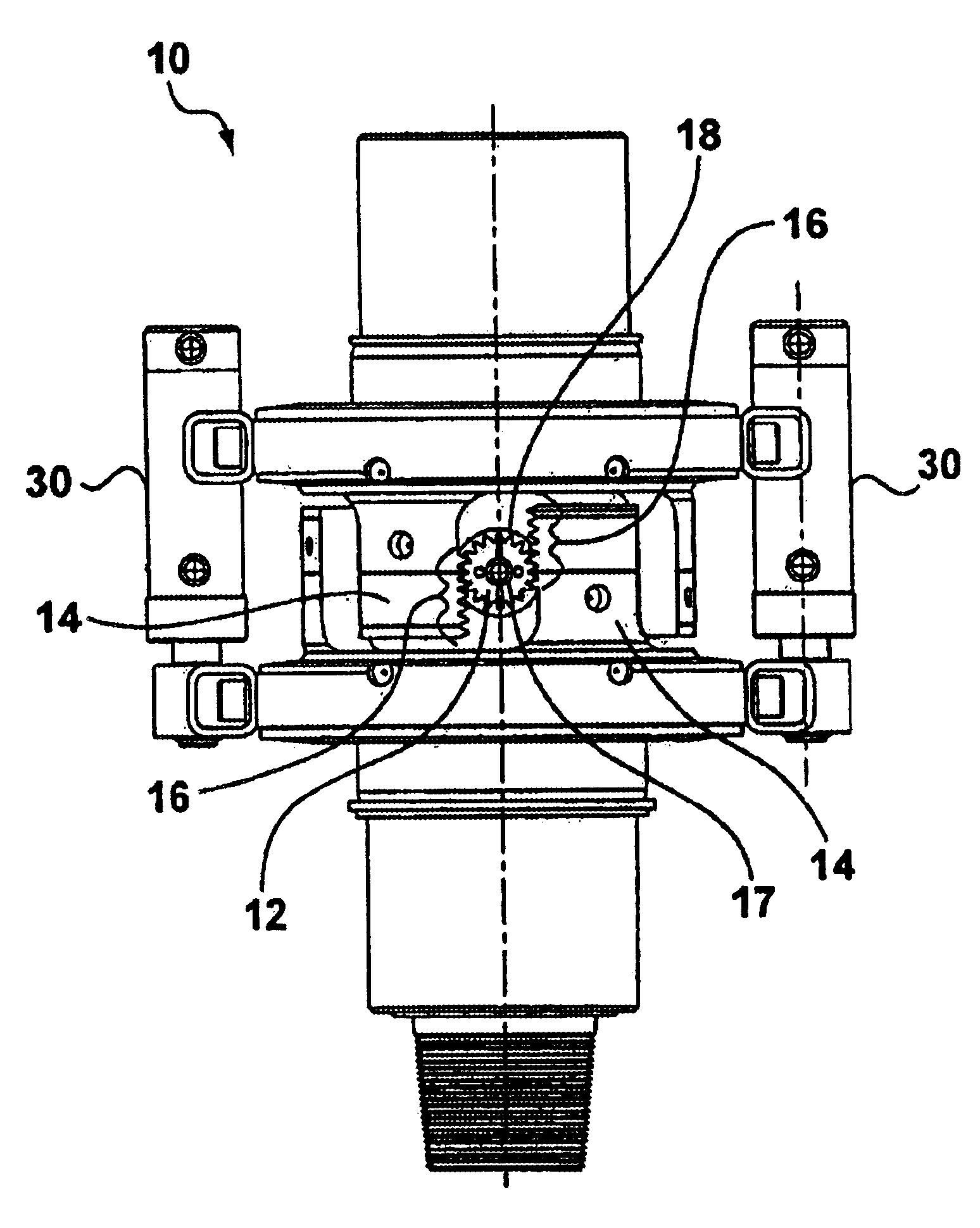
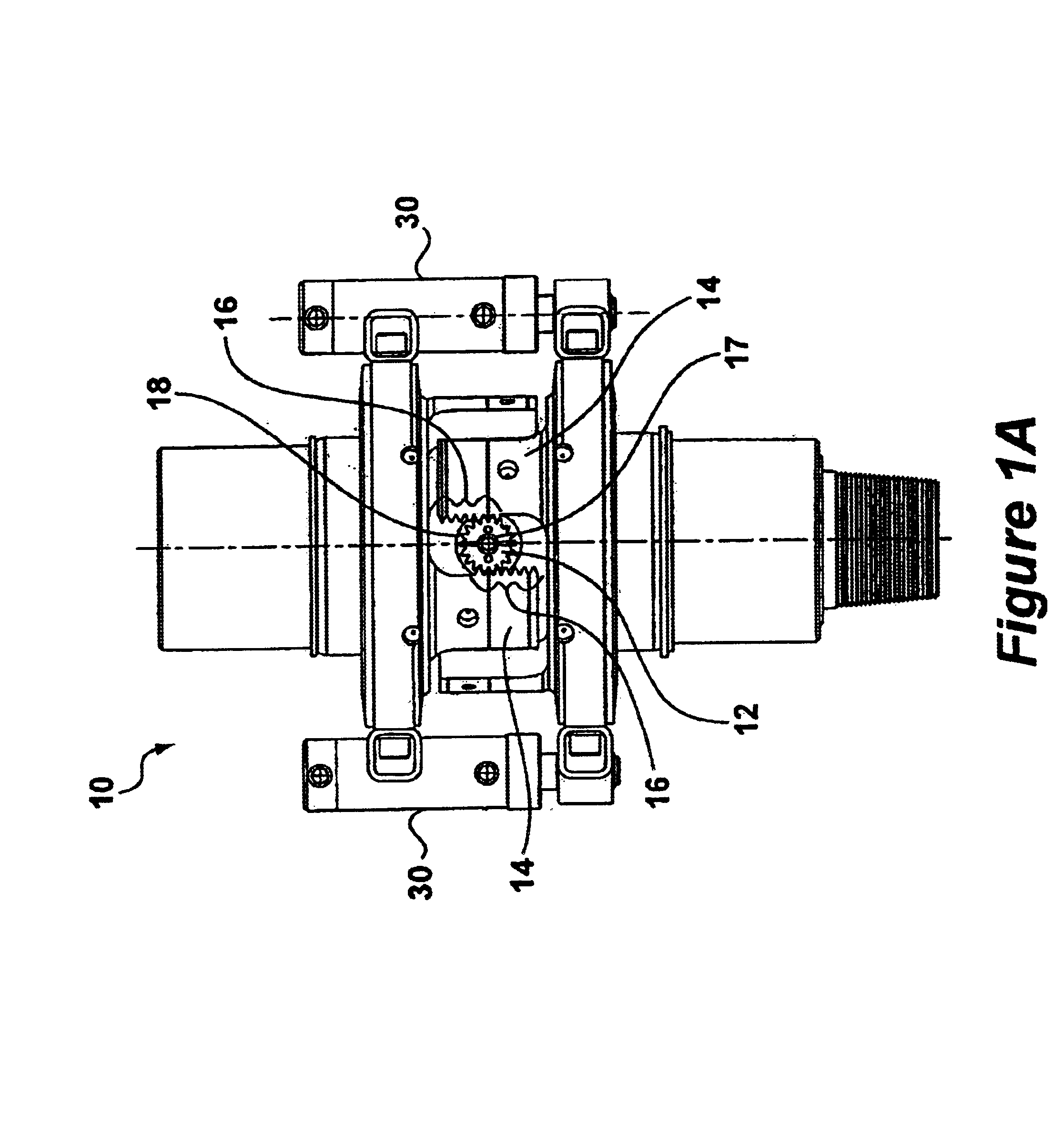
The valve actuator of the present invention is a mechanical actuator that does not include rotary seals. The actuator of the present invention includes a dual crank design, which allows a balanced couple activation to be used to turn the crank of the valve without a side load. The bearings of the valve actuator are enclosed, which protects the bearings from excessive wear and jamming, and the valve actuator may be adapted for use with valves of various manufacturers.

Shown in FIGS. 1A and 1B are side views of the valve actuator of the present invention, which is indicated generally at 10. Valve actuator 10 is coupled around the exterior of valve 11. Valve 11 is generally cylindrical in shape and includes an elongated body 13. To open or close the valve that is located with the housing of valve actuator 10, a hex key (shown in FIG. 4) must be inserted in the hex key holes 12 in each side of the valve actuator 10. By placing a hex key in the hex key hole 12 in each side of valve actuat...


PUM


Abstract

A valve actuator is provided in which a complementary set of pinions, each driven by a pair of racks, are located on opposite sides of the valve to be actuated. The racks are part of an annular bearing assembly and are coupled to one another through a hydraulic cylinder or some other displacement device. A pinion retaining sleeve is provided to shield the racks and pinions and prevents parts of the valve actuator from being thrown in operation. The piston retaining sleeve may include a maintenance aperture for installing or repairing a pinion and a second aperture for viewing the rotation of the pinion. The bearing assemblies each include a bearing housing and a bearing retainer that cooperate to shield the bearing assembly.

Description

BACKGROUND OF THE INVENTIONA portable top drive drilling unit typically includes a blowout preventer and a valve or a plurality of valves near the bottom of the top drive on the main shaft of the drill string. The blowout preventer and the valves at of the top drive drilling unit are necessary to manage the flow of fluid from the well through the drill pipe, especially in the case of an unexpected or uncontrolled flow of fluid from the well through the drill pipe. It is common to include two valves, one of which is manually controlled, the other being remotely controlled. The valves themselves may be one-quarter turn floating ball valves, and each will include a valve actuator.Because the blowout prevention valves in a top drive drilling environment may be rotating and moving along a vertical line up and down the derrick, actuation of these valves is difficult simply because the valves are not stationary. For stationary valves, in contrast, a hydraulic actuator coupled to a hydrauli...

Claims


Application Information

Patent Timeline
IPC IPC(8): F15B15/08F15B15/00F16K31/54F16K31/122F16K31/44
CPCF15B15/065F16K31/54F16K31/122
Inventor YORK, LEMUEL T.RICHARDSON, ALLAN S.KUTTEL, BEAT
Owner CANRIG DRILLING TECH
Why Eureka
Try Eureka