
Endoscope

a technology of endoscopes and endoscopes, which is applied in the field of endoscopes, can solve the problems of poor maneuverability of the structure, and achieve the effect of excellent maneuverability and readily achieving accurate observation or treatmen

Inactive Publication Date: 2005-01-04
OLYMPUS CORP
View PDF17 Cites 119 Cited by
  • Summary
  • Abstract
  • Description
  • Claims
  • Application Information

AI Technical Summary

Benefits of technology

The present invention provides an endoscope with excellent maneuverability and ease of observation or treatment. It offers the same level of bending as an endoscope with one bending portion, and also allows for independent bending of two bending portions. The endoscope has a distal portion that bends in four directions perpendicular to the insertion member's longitudinal axis, and a proximal end that bends in at least two directions perpendicular to the insertion member's longitudinal axis. The endoscope also includes first and second control members for bending the first and second bending portions, respectively. These features make the endoscope easy to use and allow for accurate observation or treatment.

Problems solved by technology

However, the structure having the first bending portion that bends in two directions like the one disclosed in the Japanese Examined Patent Application Publication No. 5-16857 has a drawback that when the first bending portion alone is used to perform the same examination as ordinary endoscopic examination, the maneuverability of the structure is poor.

Method used


Image

  • Endoscope
  • Endoscope
  • Endoscope

Examples


Embodiment Construction

An embodiment of the present invention will be described with reference to the drawings below.

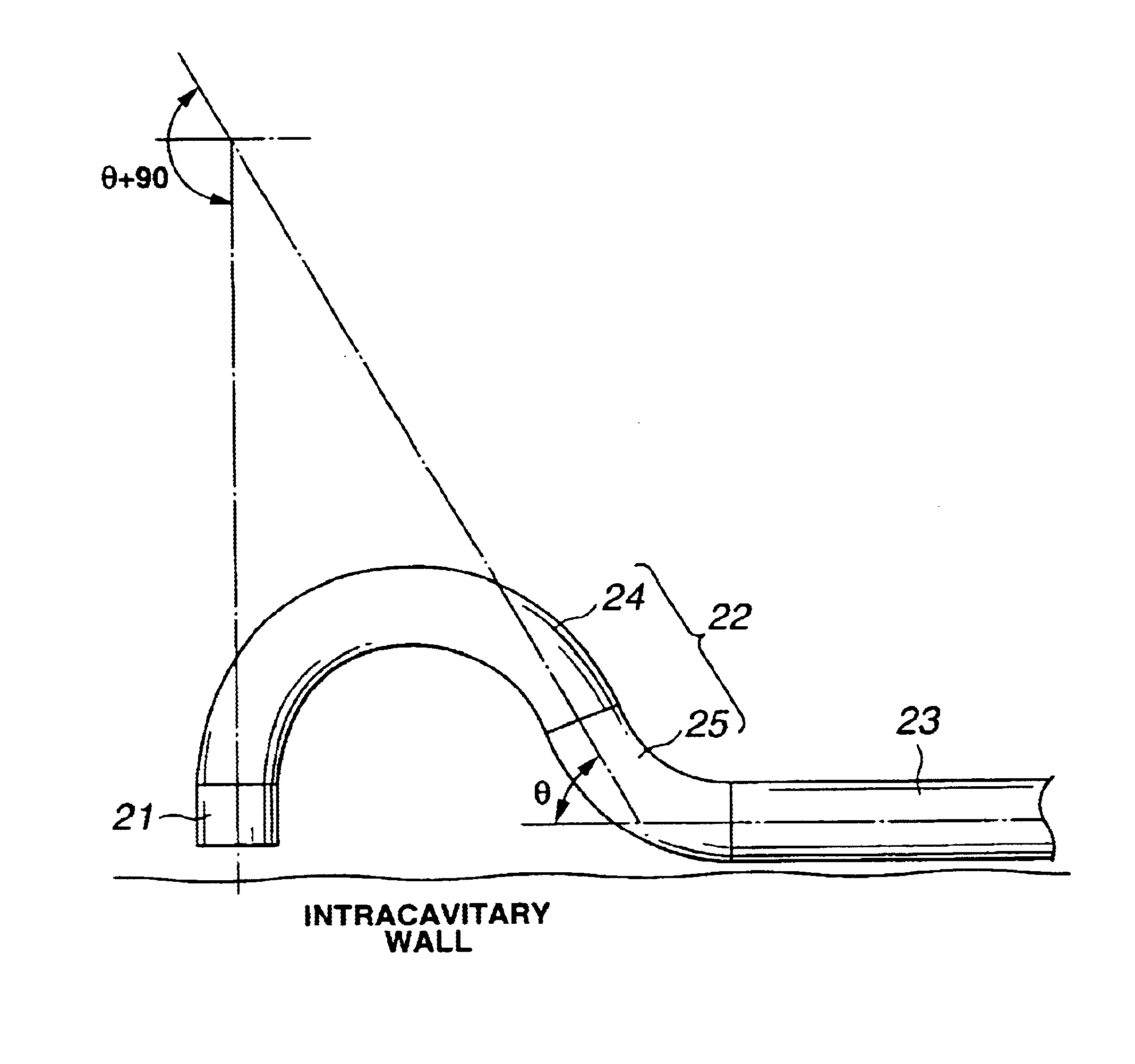
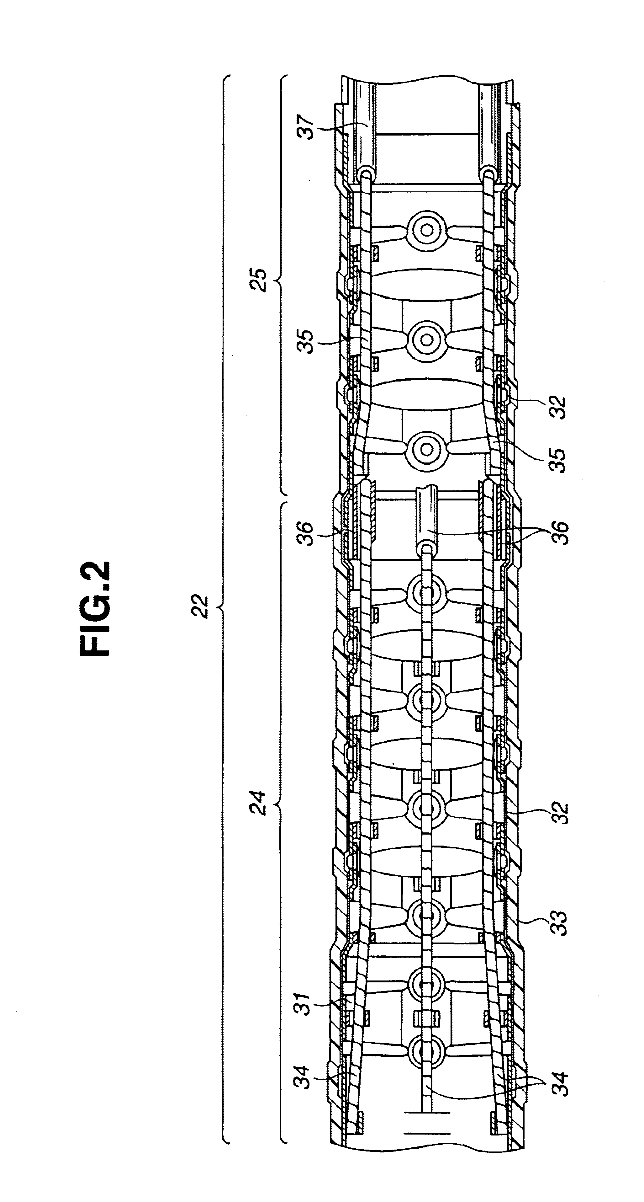
FIG. 1 to FIG. 9 are concerned with an embodiment of the present invention.

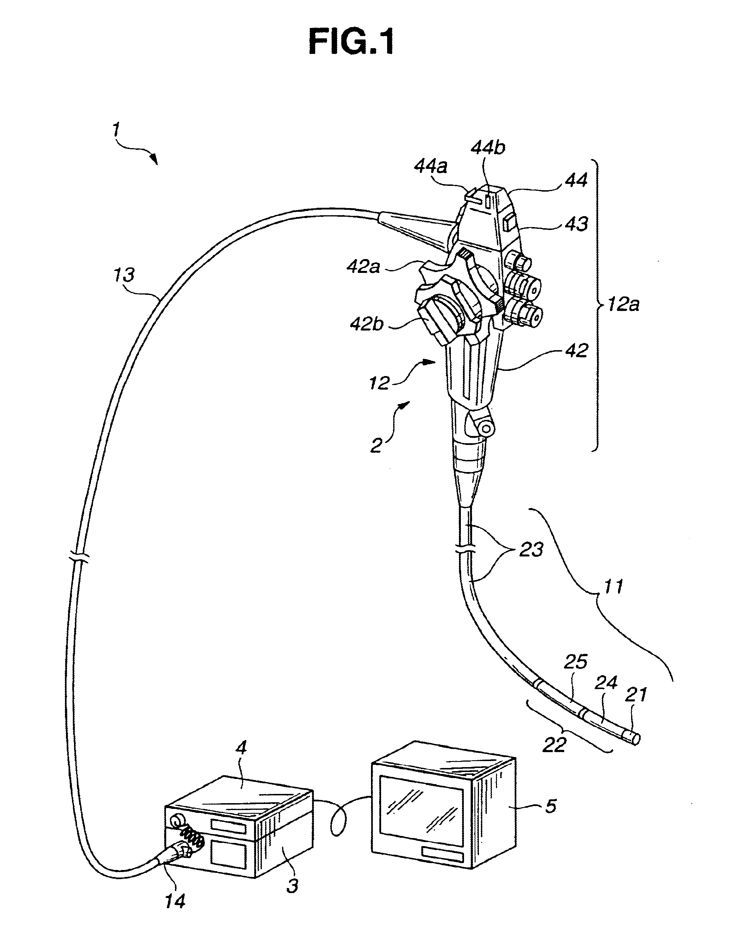
As shown in FIG. 1, an endoscope system 1 having the embodiment of the present invention consists mainly of an electronic endoscope (hereinafter simply an endoscope) 2, a light source apparatus 3, a video processor 4, and a monitor 5. The electronic endoscope 2 has an image pick-up means that is not shown. The light source apparatus 3 is connected to the endoscope 2 so that it can be disconnected freely, and supplies illumination light to the endoscope 2. The video processor 4 is connected to the endoscope 2 so that it can be disconnected freely. The video processor 4 controls the image pick-up means included in the endoscope 2 and processes a signal produced by the image pick-up means to transmit a standard video signal. The monitor 5 displays an endoscopic image according to a signal processed by the video processo...


PUM


Abstract

An endoscope has a first bending portion and a second bending portion. The first bending portion is the distal portion of an elongated insertion member and bent in four directions substantially perpendicular to the longitudinal axis of the insertion member. The second bending portion is bent in at least two directions substantially perpendicular to the longitudinal axis of the insertion member. The endoscope further includes a hand-held unit having a control section that is used to bend the first bending portion and second bending portion. The control section of the handheld unit has an angling knob that is used to bend the first bending portion, and a second angling lever that is used to bend the second bending portion.

Description

This application is based upon and claims the benefit of priority from the prior Japanese Patent Application No. 2000-302470, filed on Oct. 2, 2000 and No. 2001-232165 filed on Jul. 31, 2001 in Japan, the entire contents of which are incorporated herein by reference.BACKGROUND OF THE INVENTION1. Field of the InventionThe present invention relates to an endoscope, or more particularly, an endoscope having two bending portions of a first bending portion and a second bending portion.2. Description of the Related ArtEndoscopes have an elongated insertion member thereof inserted into the three-dimensionally complexly tortuous and narrow lumen of the stomach, the intestine, or any other organ of a living body or the three-dimensionally complexly tortuous and narrow hollow of a machine in conformity with the shape of the lumen or hollow. The insertion member of the endoscope must therefore be angled three-dimensionally finely.For example, Japanese Examined Patent Application Publication No...

Claims


Application Information

Patent Timeline
Patent Type & Authority Patents(United States)
IPC IPC(8): A61B1/005A61B1/273A61B1/31G02B23/24A61B1/00
CPCA61B1/0051A61B1/273A61B1/0055A61B1/31A61B1/0052
Inventor OGURA, TAKESHIHAMAZAKI, MASANORIKAIYA, HARUHIKONAKAMURA, TOSHIO
Owner OLYMPUS CORP
Learn More