
Ink jet recording apparatus and flushing control method used in the same

a technology of recording apparatus and flushing control, which is applied in the field ofink jet recording apparatus, can solve the problems of clogging of nozzle orifices with increased viscosity ink, generating bubbles in the capping member, and affecting printing, so as to prevent the accumulation suppress the increase of viscosity of ink, and prevent the formation of ink in the ink absorbing member

Inactive Publication Date: 2005-01-04
SEIKO EPSON CORP
View PDF14 Cites 11 Cited by
  • Summary
  • Abstract
  • Description
  • Claims
  • Application Information

AI Technical Summary

Benefits of technology

The present invention is directed to solve the problems arising from the flushing operation, and has an object to provide an flushing control method which selects an operation mode to execute a flushing process in a state that the nozzle formation face of the recording head is sealed with the capping member in particular when a flushing amount is large, and solves the problem of the accumulation of the solidified specific color ink, and ink jet recording apparatus which guarantees a high print quality for a long time.
Further, the easy-to-solidify ink and the hard-to-solidify ink are mixed through the execution of the above-mentioned control. Therefore, solidification and accumulation of the ink in the ink absorbing member can be prevented. The waste ink is swiftly discharged by suction member.

Problems solved by technology

Therefore, the nozzle orifices are frequently clogged, and this results in improper printing.
Accordingly, those nozzle orifices are frequently clogged with the ink of increased viscosity.
In the pigment contained ink, a problem that bubbles are generated in the capping member arises.
The generated bubbles will destroy the meniscus formed at the nozzle orifices, so that ejection failure occurs.
The ink mist floating within the apparatus stick to the guide rod for moving the carriage or the like, soils the same, thereby making the carriage movement difficult.
As a result, the normal operation of the recording apparatus is lost.
When the recording head is sealed with the capping member, there is a chance that the accumulated ink reaches the nozzle formation face.

Method used


Image

  • Ink jet recording apparatus and flushing control method used in the same
  • Ink jet recording apparatus and flushing control method used in the same
  • Ink jet recording apparatus and flushing control method used in the same

Examples


Embodiment Construction

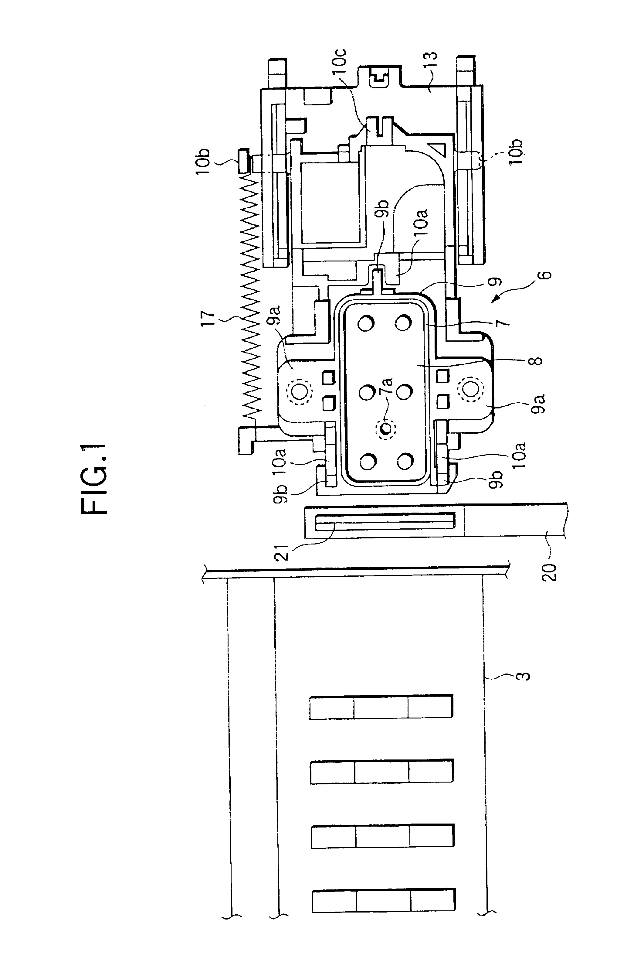
Ink jet recording apparatus constructed according to the present invention will be described with reference to the accompanying drawings.

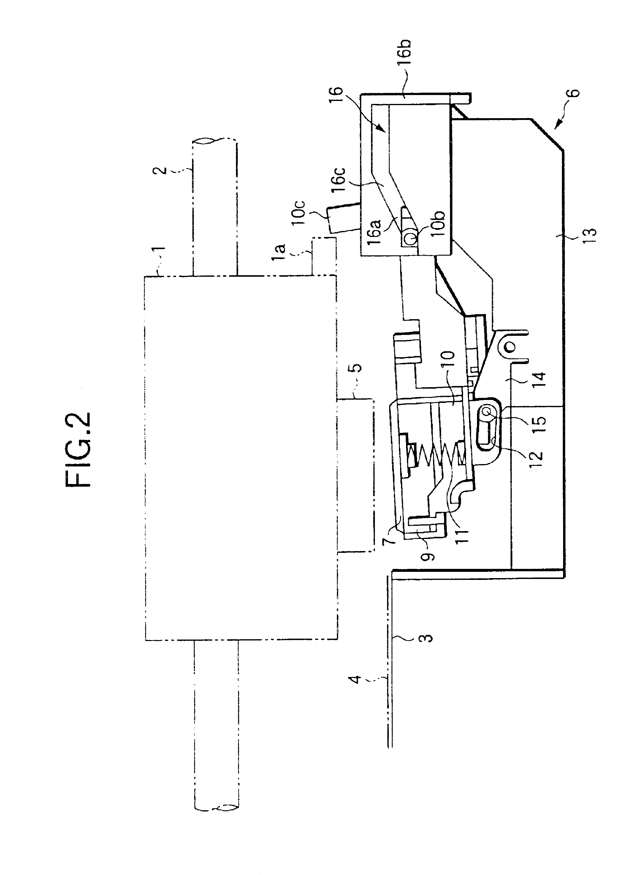
Referring to FIGS. 2 and 3, a carriage 1 is guided by a guide rod 2 and moved in a longitudinal direction of a platen 3 while facing and being aligned in parallel with the same. The carriage 1 is coupled to a part of a timing belt, which is reciprocatively moved by a carriage motor to be given later, and reciprocatively moved along the guide rod 2.

The carriage 1 is mounted such that a recording head 5 faces a recording sheet 4 of paper located on an upper face of the platen 3. To print, ink is introduced into the recording head 5, and the recording head ejects ink drops onto the recording sheet 4 on the platen 3 in accordance with bit map data corresponding to print data.

A capping unit 6 capable of sealing the nozzle formation face of the recording head 5 is located in a non-print area (home position), which is formed at one end of the recording ap...


PUM


Abstract

An ink jet recording head is provided with a nozzle formation face on which nozzles for ejecting ink drops in accordance with print data are formed. A capping member for sealing the nozzle formation face has an inner space formed with a bottom. An ink absorbing member is provided on the bottom of the inner space. In a first flushing mode, ink drops are ejected into the capping member in a state that the nozzle formation face is sealed by the capping member. In a second flushing mode, ink drops are ejected into the capping member in a state that the capping member is separated from the nozzle formation face. Either the first flushing mode or the second flushing mode is selectively performed.

Description

BACKGROUND OF THE INVENTIONThe present invention relates to ink jet recording apparatus provided with a recording head for ejecting ink drops in accordance with print data. More particularly, the invention relates to a management technique which solves a problem arising from executing a flushing operation to idly eject ink drops to a capping member for hermetically closing a nozzle formation face of the recording head, and which suppresses the solidification of the ink and the like within the capping member by appropriately managing a flushing amount.Generally, the ink jet recording apparatus is provided with the ink jet recording head for receiving ink from ink cartridge, and a sheet feeder for moving a recording sheet of paper relative to the recording head. An image is recorded on the recording sheet in a manner that ink drops are ejected onto the recording sheet in accordance with print data while moving the recording head in the main scanning direction. In the recording head, t...

Claims


Application Information

Patent Timeline
IPC IPC(8): B41J2/165B41J2/175
CPCB41J2/16505B41J2/16526B41J2/16523B41J2/16508
Inventor MITSUZAWA, TOYOHIKOKOMATSU, KATSUHIRO
Owner SEIKO EPSON CORP
Learn More