
Sand monitoring within wells using acoustic arrays

Active Publication Date: 2005-01-04
WEATHERFORD TECH HLDG LLC
View PDF102 Cites 137 Cited by
  • Summary
  • Abstract
  • Description
  • Claims
  • Application Information

AI Technical Summary

Problems solved by technology

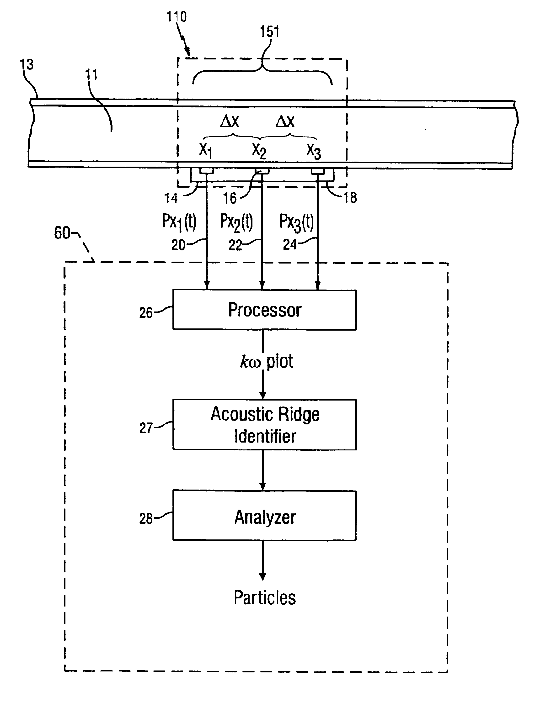
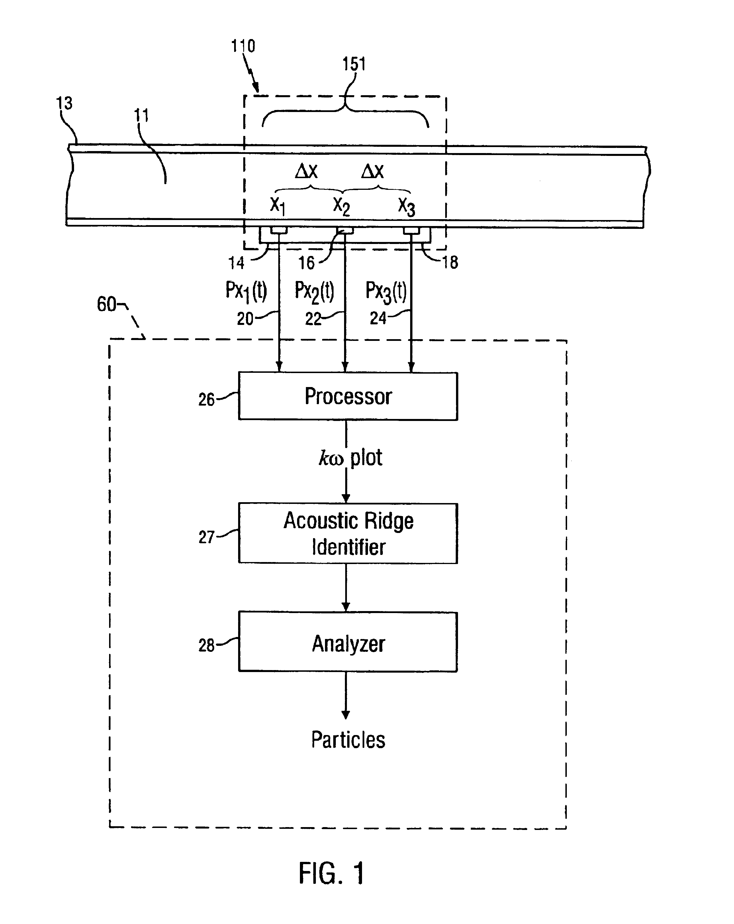
These pressure variations are caused by acoustic noise generated by typical background noises of the well production environment and from sand particles flowing within the fluid.

Method used


Image

  • Sand monitoring within wells using acoustic arrays
  • Sand monitoring within wells using acoustic arrays
  • Sand monitoring within wells using acoustic arrays

Examples


Embodiment Construction

raph of power versus velocity with a peak corresponding to the fluid sound speed, according to the present invention.

[0014]FIG. 4 illustrates kω plots suspected of indicating the presence of sand falling through a well whose production has been halted.

DETAILED DESCRIPTION OF EMBODIMENTS OF THE INVENTION

[0015]In the disclosure that follows, in the interest of clarity, not all features of actual implementations are described in this disclosure. It will of course be appreciated that in the development of any such actual implementation, as in any such project, numerous engineering and design decisions must be made to achieve the developers' specific goals, e.g., compliance with mechanical and business related constraints, which will vary from one implementation to another. While attention must necessarily be paid to proper engineering and design practices for the environment in question, it should be appreciated that the development of a method to detect particles, such as sand, flowing...


PUM


Abstract

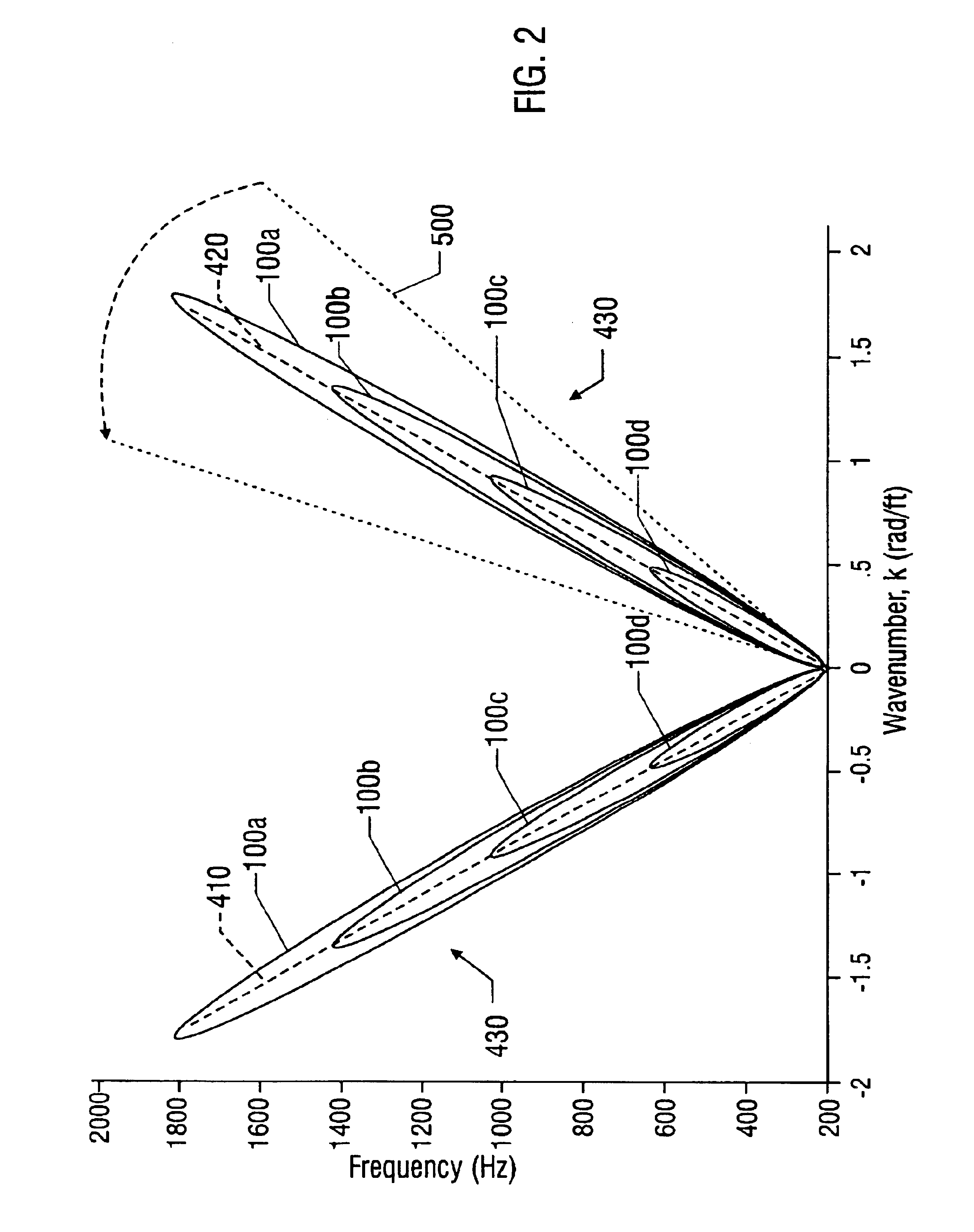
A method for detecting the presence of particles, such as sand, flowing within a fluid in a conduit is disclosed. At least two optical sensors measure pressure variations propagating through the fluid. These pressure variations are caused by acoustic noise generated by typical background noises of the well production environment and from sand particles flowing within the fluid. If the acoustics are sufficiently energetic with respect to other disturbances, the signals provided by the sensors will form an acoustic ridge on a kω plot, where each data point represents the power of the acoustic wave corresponding to that particular wave number and temporal frequency. A sand metric then compares the average power of the data points forming the acoustic ridge to the average power of the data points falling outside of the acoustic ridge. The result of this comparison allows one to determine whether particles are present within the fluid. Furthermore, the present invention can also determine whether the generated acoustic noise is occurring upstream or downstream of the sensors, thus giving an indication of the location of the particles in the fluid relative to the sensors.

Description

FIELD OF THE INVENTION[0002]This invention relates generally to fluid sensing, and more particularly to detecting particles flowing in a fluid within a conduit.BACKGROUND OF THE INVENTION[0003]The production of particles, such as sand, concerns operators of oil / gas wells because of the possible catastrophic consequences on production. (In this disclosure, “sand should be understood as referring to solid particulate matter as would be found in an oil / gas well, without particular regard to its size or diameter). The production of sand may start at relatively minor levels, but then may rapidly increase resulting in clogged well lines that effectively “fill in” the well and halt production. Sand can also contaminate the separator tanks, which typically connect to other producing wells. When this occurs, the production of all oil wells feeding into the separator tanks must be halted. Furthermore, once sand has entered into the completion equipment, corrosion and / or erosion is likely, res...

Claims


Application Information

Patent Timeline
IPC IPC(8): G01N15/06G01F1/712G01F1/704G01F1/708G01F1/7082G01N29/04
CPCG01F1/7082G01F1/712G01N15/06G01N29/046G01N2291/02872G01N2291/02416G01N2291/02836
Inventor GYSLING, DANIEL L.LOOSE, DOUGLAS H.
Owner WEATHERFORD TECH HLDG LLC
Learn More