
Bottom hole assembly

a bottom hole and assembly technology, applied in the direction of borehole/well accessories, drilling casings, drilling pipes, etc., can solve the problems of coiled tubing being unable to remove the bottom hole assembly, and affecting the fracing process

Inactive Publication Date: 2004-12-21
BAKER HUGHES INC
View PDF17 Cites 99 Cited by
  • Summary
  • Abstract
  • Description
  • Claims
  • Application Information

AI Technical Summary

Benefits of technology

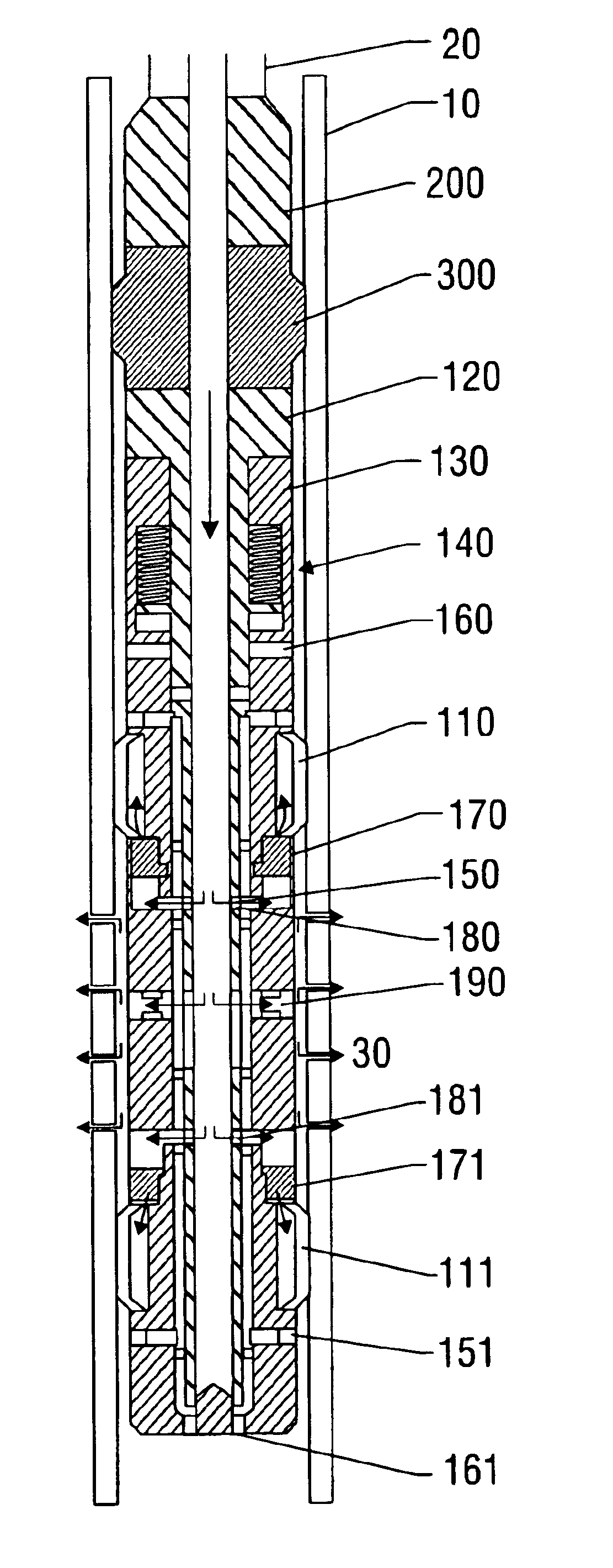
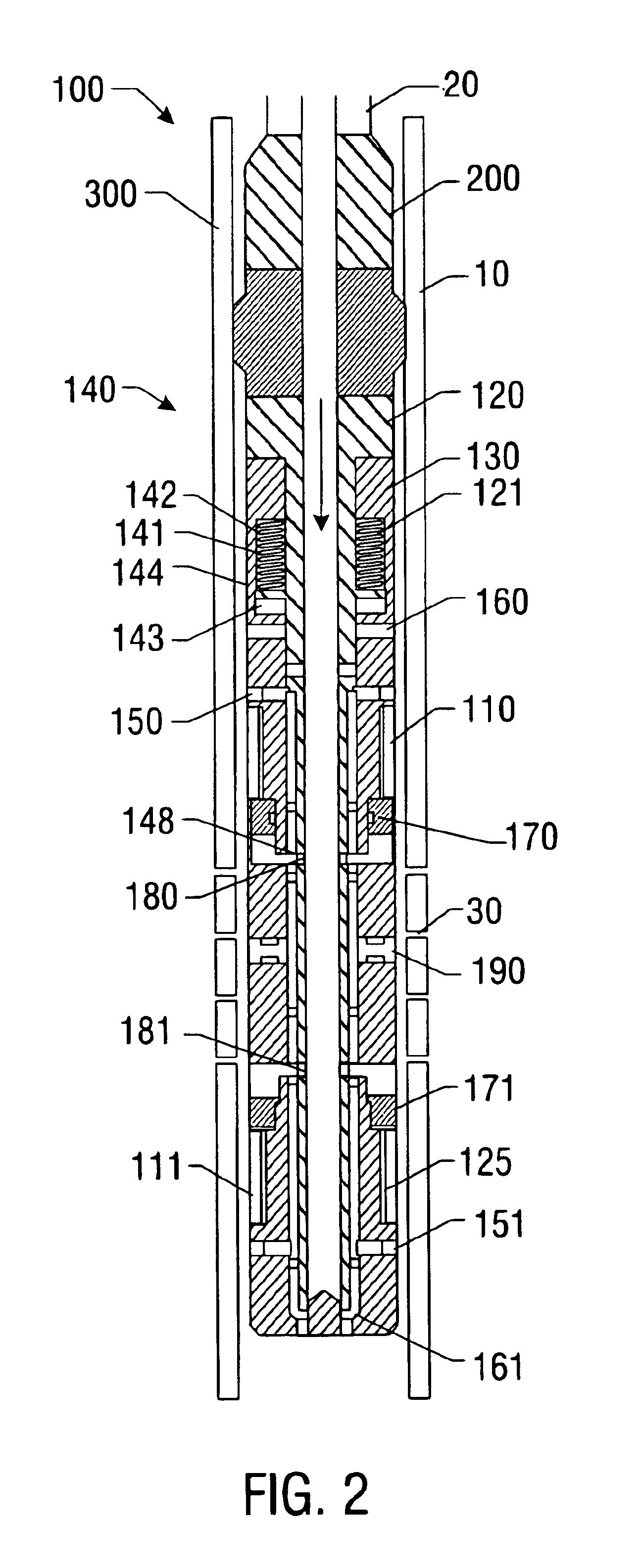
The present invention relates to a bottom hole assembly for use in wellbores to isolate different zones and prevent fluid communication between them. The invention solves problems associated with using coiled tubing for fracturing multiple zones, such as the risk of the bottom hole assembly becoming stuck in the wellbore casing and the difficulty of retrieving the coiled tubing. The invention also addresses the issue of sand build-up and the potential for communication between zones during fracturing operations. The invention provides a straddle packer that can be used with coiled tubing and has improved resistance to sand build-up.

Problems solved by technology

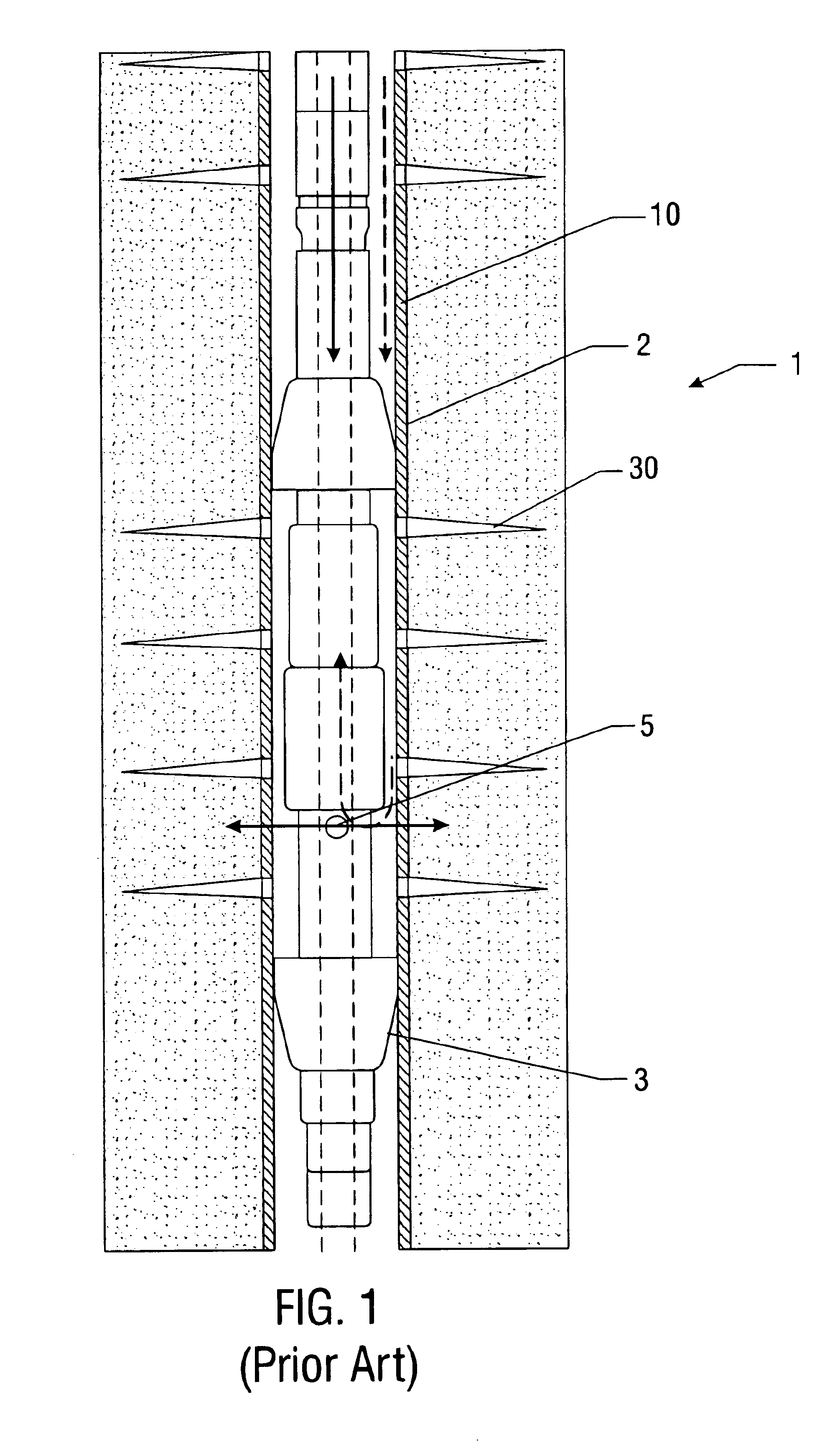
However, utilizing coiled tubing to fracture multiple zones can be problematic.
Thus, coiled tubing may be unable to remove a bottom hole assembly that becomes lodged in the casing.
Additionally, the fracing process may be compromised if the proppant is underflushed such that sand slurry remains within the bottom hole assembly and even the coiled tubing.
Further, in the event that the well's casing integrity is breached, it is possible that proppant could be pumped into the well above the zone being treated, leading to the possibility of the coiled tubing being stuck in the hole.
The tool may occupy almost the full cross-sectional area of the well casing which increases the risk of the tool or bottom hole assembly being lodged or stuck in the wellbore casing.
Once the bottom hole assembly becomes lodged, due to excess sand from the proppant becoming lodged between the bottom hole assembly and the wellbore casing, the tensile strength of the coiled tubing generally is not strong enough to be able to dislodge the bottom hole assembly.
These procedures increase the time and cost of fracing a zone.
Coiled tubing operations in deeper wells present another problem to operators trying to retrieve the bottom hole assembly and / or coiled tubing from a deep well.
However, in relatively deep wells, the weight of the coiled tubing detracts from the maximum force that may be applied to the release tool.
Thus, if the release force is set to low, the bottom hole assembly may be mistakenly released while operating in shallow portions of the well.
However, if the release force is set high enough so that the bottom hole assembly will not be inadvertently released in the shallow portion of the well, then, when the bottom hole assembly is at deeper portions of the well, the coiled tubing may not have sufficient strength to overcome the weight of the coiled tubing to apply the required release force.
Thus, the bottom hole assembly may become stuck in a deep well and the coiled tubing may not be able to retrieve it.
Fracing with coiled tubing can present yet another problem.
Communication between zones occurs due to poor cement behind the casing.
However, when used in a fracing procedure, these valve become susceptible to becoming inoperable due to sand build up around the valves.
This type of straddle packer typically can only be utilized with relatively low frac pressures, in lower temperatures, and in wellbores of shallower depth.
However, when zones to be fraced are not relatively shallow, the formation pressure is not high enough to support a column of fluid in the annulus from the zone to surface.
Thus, the reverse circulation of fluid to remove excess sand from the tool is not possible, again increasing the likelihood that the packer may become lodged in the casing 10.
However, without this column of fluid, such as in deep wells, the operator has no way of monitoring what is transpiring downhole which further increases the changes of the bottom hole assembly becoming lodged.
Another problem with fracing deeper wells with coiled tubing occurs when sand slurry is pumped through the bottom hole assembly at high flow rates.
These high flow rates may cause erosion of the casing.

Method used


Image

  • Bottom hole assembly
  • Bottom hole assembly
  • Bottom hole assembly

Examples


Embodiment Construction

Illustrative embodiments of the invention are described below as they might be employed in the fracing operation. In the interest of clarity, not all features of an actual implementation are described in this specification. It will of course be appreciated that in the development of any such actual embodiment, numerous implementation specific decisions must be made to achieve the developers' specific goals which will vary from one implementation to another. Moreover, it will be appreciated that such a development effort might be complex and time-consuming, but would nevertheless be a routine undertaking for those of ordinary skill in the art having the benefit of this disclosure. Further aspects and advantages of the various embodiments of the invention will become apparent from consideration of the following description and drawings.

The following examples are included to demonstrate preferred embodiments of the invention. It should be appreciated by those of skill in the art that t...


PUM


Abstract

A bottom hole assembly for use with fracturing or fracing a wellbore using coiled tubing is described having a first packing element and a second packing on a mandrel. The bottom hole assembly may be run into the wellbore such that the packing elements straddle the zone to be fraced. Also described is a timing mechanism to prevent the closing of dump ports before the bottom hole assembly may be flushed of the sand. A release tool is described that allows an operator to apply force to the coiled tubing to dislodge a bottom hole assembly without completely releasing the bottom hole assembly. Also disclosed is a collar locator capable of being utilized in a fracing process. Methods of using the above described components are also disclosed.

Description

1. Field of the InventionThe present invention relates generally to packers for use in wellbores. More particularly, this invention relates to a bottom hole assembly for use with coiled tubing for the purpose of testing or fracturing ("fracing") a well.2. Description of the Related ArtIn the drilling and production of oil and gas wells, it is frequently necessary to isolate one subterranean region from another to prevent the passage of fluids between those regions. Once isolated, these regions or zones may be fraced as required.Many stimulation techniques for given types of wells are better suited to using coiled tubing as opposed to solid mechanical structures such as wirelines. Generally, it is known to attach a packing device, such as a straddle packer, to a line of coiled tubing and run the packing device downhole until the desired zone is reached. Once positioned, the fracing proppant or sand slurry may be forced into the zone.However, utilizing coiled tubing to fracture multip...

Claims


Application Information

Patent Timeline
Patent Type & Authority Patents(United States)
IPC IPC(8): E21B43/26E21B17/00E21B23/00E21B17/20E21B34/06E21B34/00E21B33/12E21B23/06E21B34/10E21B23/04E21B23/02E21B34/08E21B33/124E21B43/25E21B17/06
CPCE21B17/06E21B17/20E21B23/02E21B23/06E21B43/26E21B34/063E21B34/085E21B34/101E21B33/1243
Inventor RAVENSBERGEN, JOHN EDWARDNAUMANN, ANDREVACIK, LUBOSLAMBERT, MITCHWILDE, GRAHAM
Owner BAKER HUGHES INC
Learn More