
Conveying apparatus

a technology of conveying apparatus and moving shaft, which is applied in the direction of lighting and heating apparatus, charge manipulation, furniture, etc., can solve the problems of large thrust loss, complex control, and large structure complexity of the entire apparatus

Inactive Publication Date: 2004-11-09
DAIFUKU CO LTD
View PDF5 Cites 28 Cited by
  • Summary
  • Abstract
  • Description
  • Claims
  • Application Information

AI Technical Summary

Benefits of technology

This design allows for smooth and secure operation in U-turn path sections with reduced torsional stress and overall length of load bars, eliminating the need for enlarged radii and separate driving systems, thus enhancing the practicality and efficiency of the conveying apparatus.

Problems solved by technology

The difference between the directions causes a great loss of thrust.
It is difficult to thrust these carriers in the U-turn path sections of a traveling path.
Thus the entire apparatus is complex in structure, expensive, and complex to control.

Method used


Image

  • Conveying apparatus
  • Conveying apparatus
  • Conveying apparatus

Examples


Embodiment Construction

Exemplary embodiments of the present invention are described below with reference to the accompanying drawings. It should be apparent to those skilled in the art that the described embodiments of the present invention provided herein are illustrative only and not limiting, having been presented by way of example only. All features disclosed in this description may be replaced by alternative features serving the same or similar purpose, unless expressly stated otherwise. Therefore, numerous other embodiments of the modifications thereof are contemplated as falling within the scope of the present invention as defined herein and equivalents thereto. Hence, use of absolute terms, such as, for example, "will," "will not," "shall," "shall not," "must," and "must not," are not meant to limit the scope of the present invention as the embodiments disclosed herein are merely exemplary.

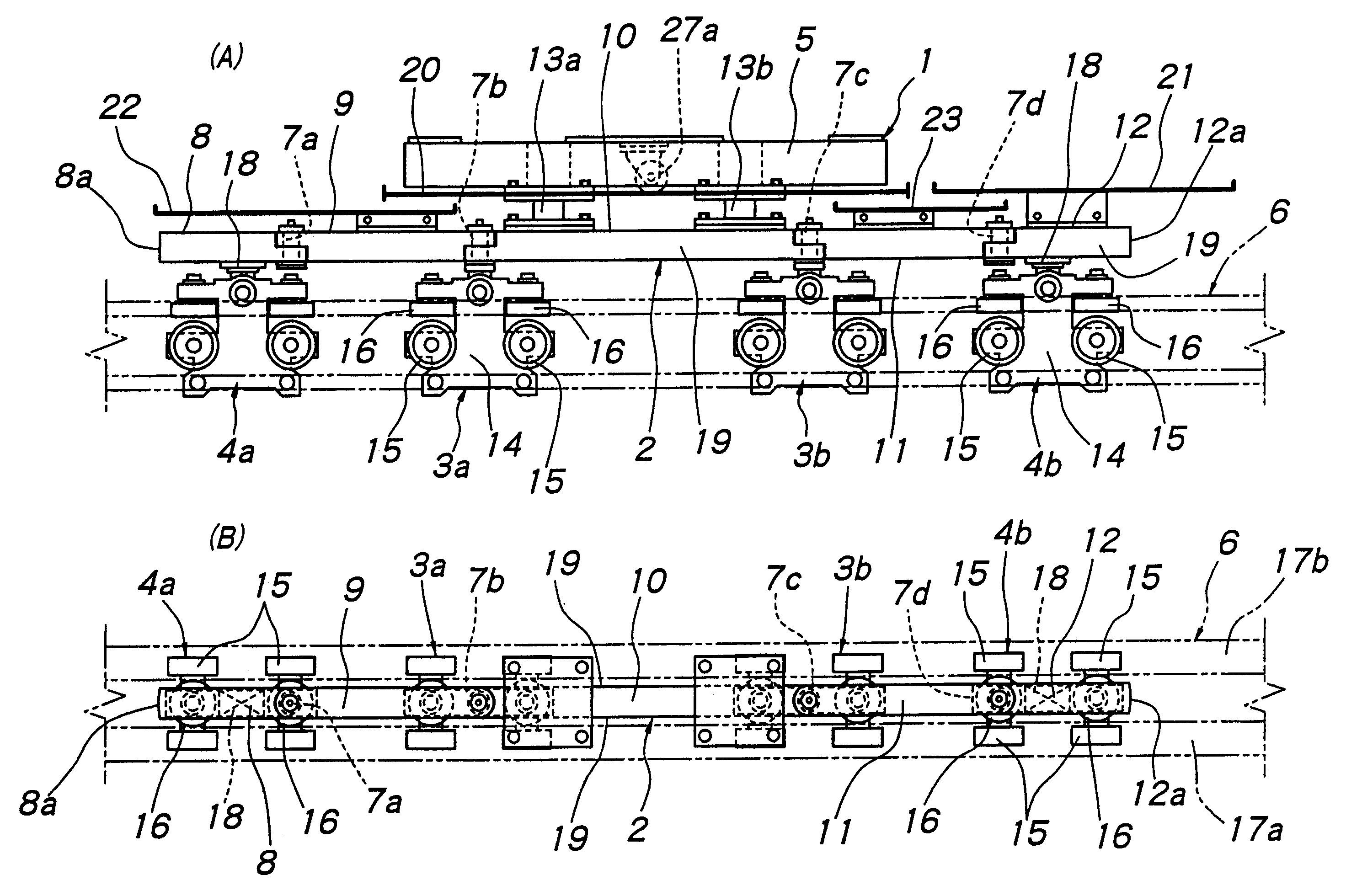
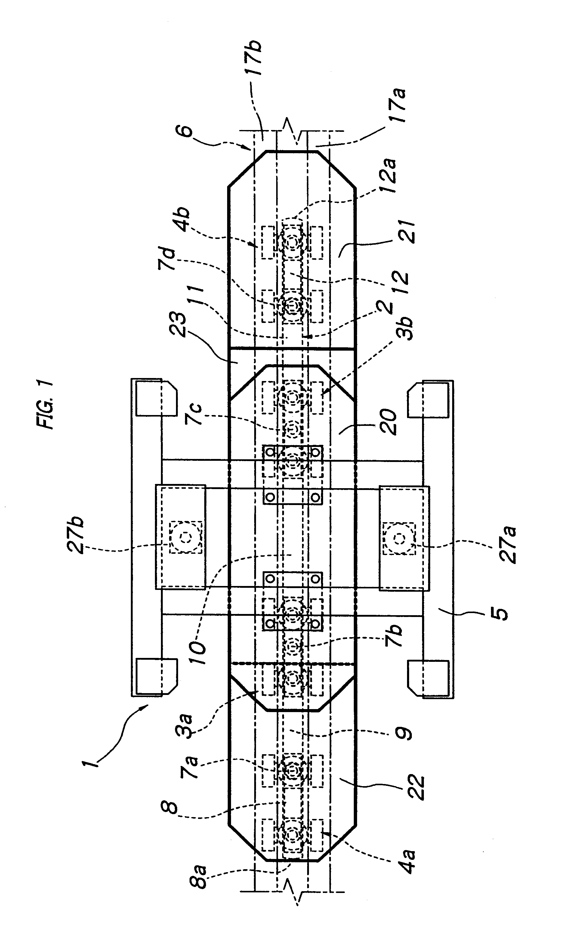
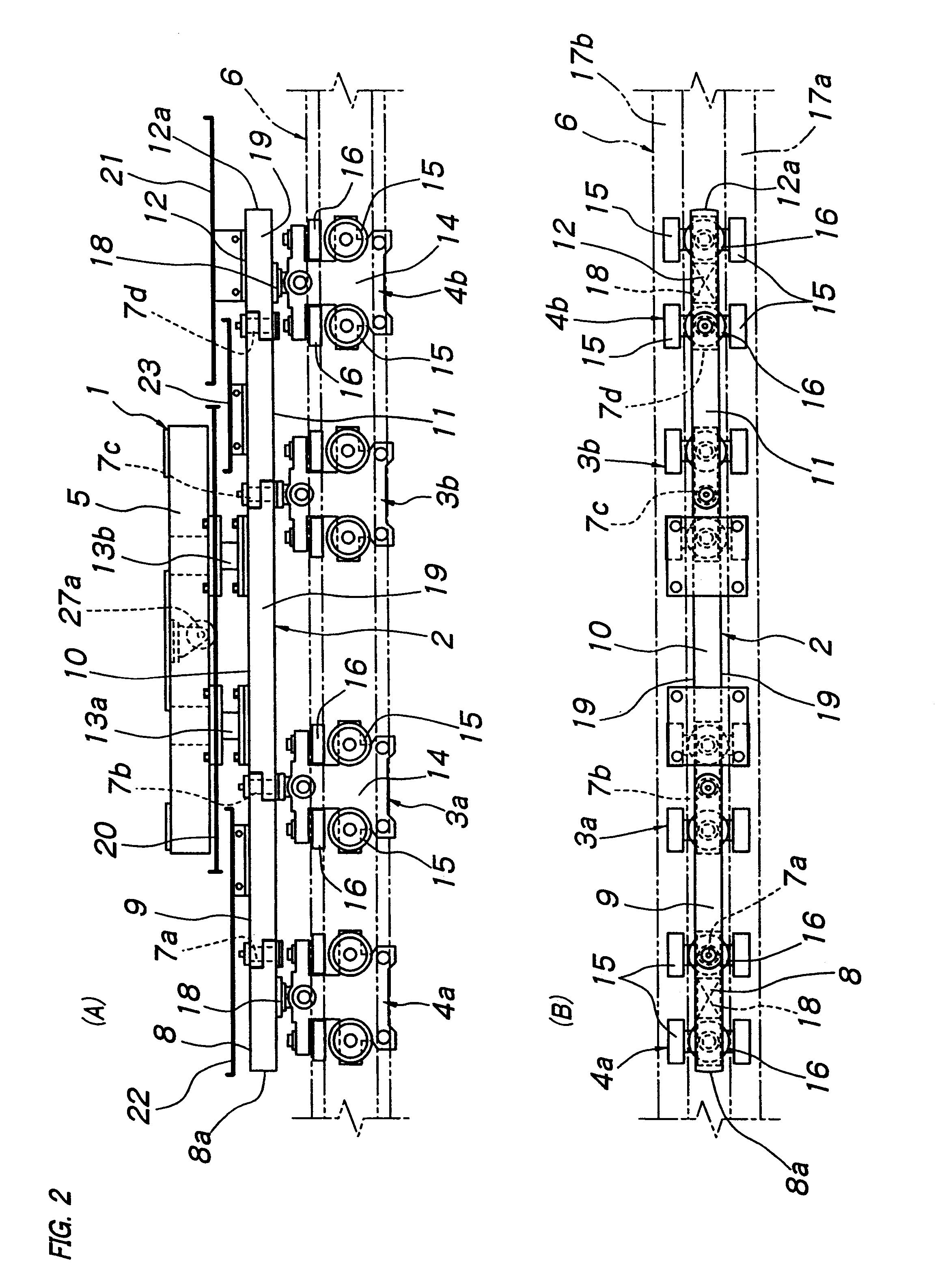
With reference to FIGS. 1-3, a carrier 1 consists of a load bar assembly 2, a front load trolley 3a, a rear l...


PUM


Abstract

A conveying apparatus suitable for driving a number of carriers in such a manner that the front end of each carrier thrusts the rear end of the preceding carrier is provided. The conveying apparatus comprises a guide rail and carriers. The rail includes a U-turn path section. Each carrier includes a load bar assembly including at least three load bars connected end-to-end by vertical pivot shafts in such a manner that the bars can pivot horizontally relative to each other. Each carrier also includes a load support supported by the associated middle load bar. Each carrier further includes a front trolley supporting at least the front end load bar and a rear trolley supporting at least the rear end load bar. The trolleys are supported movably on and guided by the guide rail. The trolleys are fixed to and in parallel with the end load bars. The free ends of the end load bars protrude from the front end of the front trolley and the rear end of the rear trolley so that the free end of the front end load bar of each carrier and the free end of the rear end load bar of the preceding carrier can contact together in the U-turn path section.

Description

The present invention relates to a conveying apparatus suitable for driving a number of carriers in such a manner that the front end of each carrier thrusts the rear end of the preceding carrier.PRIOR ARTIn prior art thrust-drive conveying apparatuses, the front end of a carrier thrusts the rear end of the preceding carrier along a traveling path, which includes linear and U-turn path sections. Travel in the linear path sections occurs without thrust problems. In the U-turn path sections, adjacent carriers are not aligned linearly, but angled to each other. The direction of the thrust acting on each of the mutually angled carriers differs from the direction in which the preceding carrier moves. The difference between the directions causes a great loss of thrust. Accordingly, in order to thrust the carriers smoothly and securely in the U-turn path sections, it is necessary to maximize the radius of curvature of these sections and drive the carriers with great thrust. One type of prio...

Claims


Application Information

Patent Timeline
Patent Type & Authority Patents(United States)
IPC IPC(8): B61B13/12B61B13/00B65G35/06B65G47/60
CPCB65G35/06B61B13/127B65G47/60
Inventor NISHIHARA, SHIGEYOSHI
Owner DAIFUKU CO LTD
Learn More