
Method for protecting a DC generator against overvoltage

a technology for dc generators and overvoltages, applied in the direction of dc-dc conversion, power conversion systems, instruments, etc., can solve problems such as the risk of catastrophic damage to equipment, and achieve the effect of avoiding fatal breakdowns of modems

Inactive Publication Date: 2004-11-02
GENERAL ELECTRIC TECH GMBH
View PDF15 Cites 12 Cited by
  • Summary
  • Abstract
  • Description
  • Claims
  • Application Information

AI Technical Summary

Benefits of technology

The present invention provides a method for protecting power supply units from breakdowns due to starting without a load being connected. The method also increases the reliability of electrostatic precipitators by reducing the risk of stoppages due to rectifier breakdowns resulting from starting without the load being connected. The method involves measuring the voltage across the output of a current generator during an initial phase and comparing it with a voltage limit value. The current generation is interrupted and a loss of load is indicated if any one of the voltages across the output of the current generator measured during the initial phase exceeds the voltage limit value.

Problems solved by technology

For modem voltage transducers of the type called current generators, a loss of load results in the risk of catastrophic damage to the equipment.

Method used


Image

  • Method for protecting a DC generator against overvoltage
  • Method for protecting a DC generator against overvoltage
  • Method for protecting a DC generator against overvoltage

Examples


Embodiment Construction

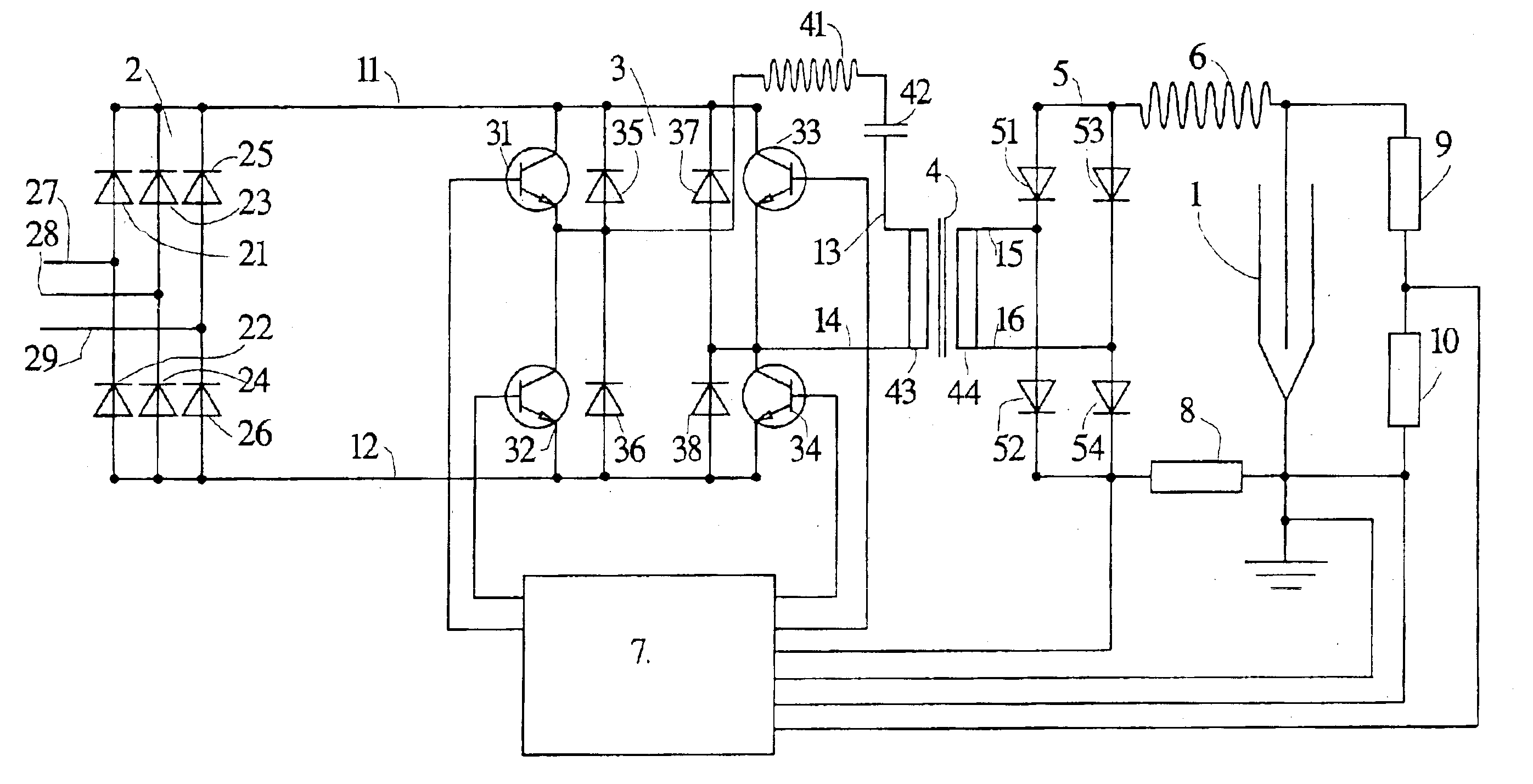
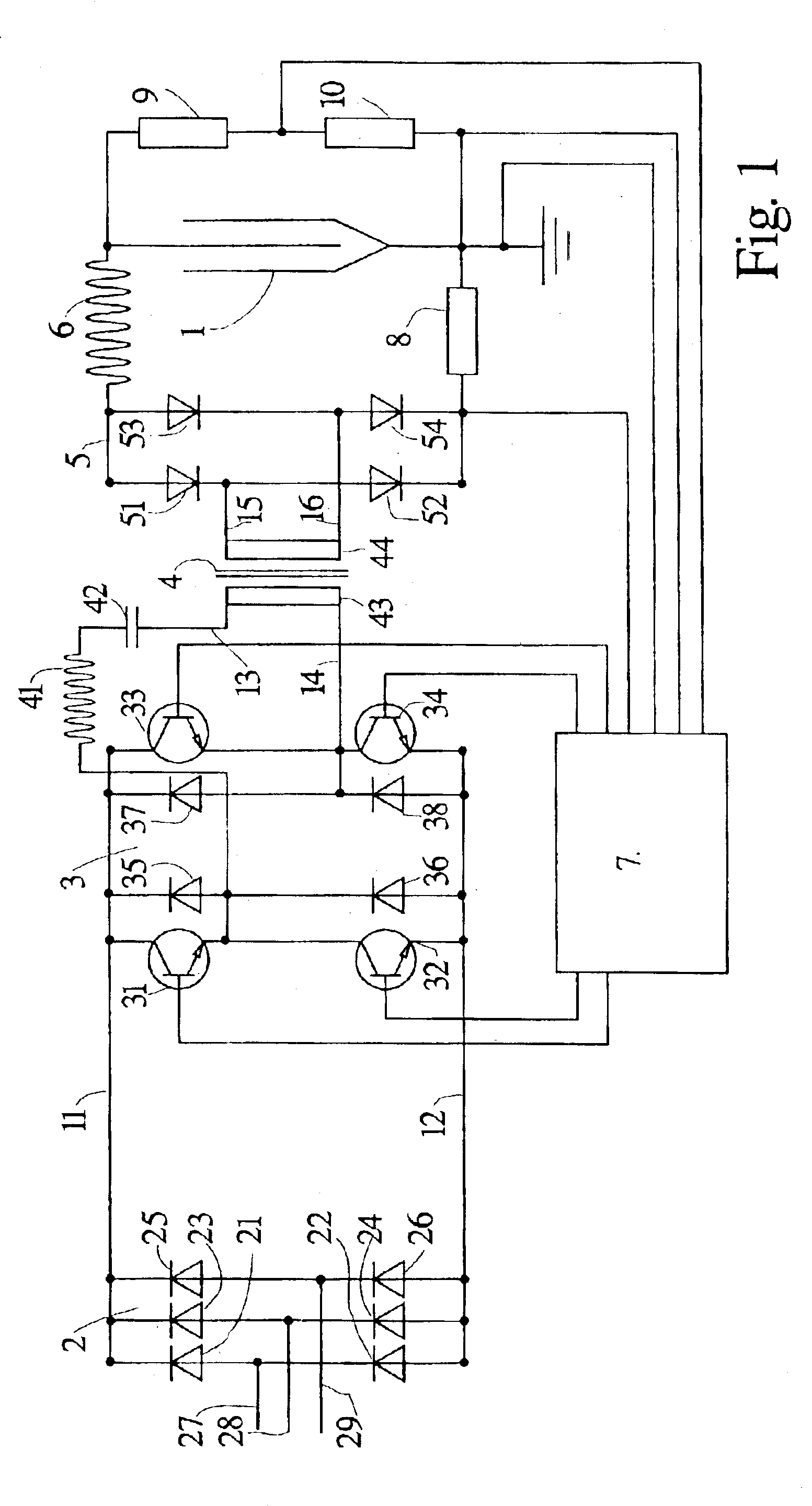
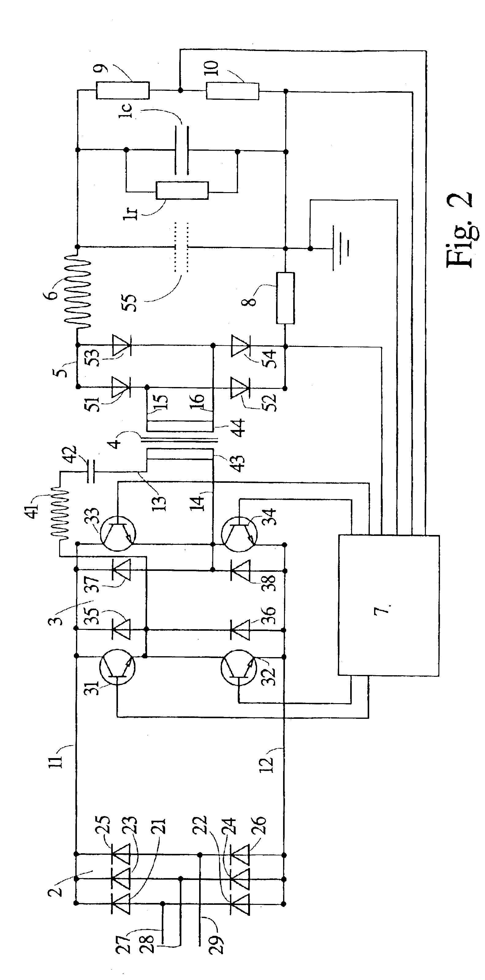
FIG. 1 shows in an outline circuit diagram a current generator in the form of a voltage transducing device that supplies high-voltage direct current to a precipitator 1. The device consists of a three-phase rectifier bridge 2, a pulse generator 3, a transformer 4, a full wave rectifier bridge 5 for single-phase, a choke 6 and control equipment 7 with associated measurement resistors 8, 9 and 10.

The three-phase rectifier bridge 2 comprises six diodes 21 to 26 and is connected via three conductors 27, 28, 29 to a normal three-phase AC network.

The pulse generator 3 consists of four transistors 31-34 and four diodes 35-38. The transistors are controlled by their bases being connected to the control equipment 7.

Between the pulse generator 3 and the primary winding 43 of the transformer 4, a series resonance circuit is connected consisting of a choke 41 and a capacitor 42.

The full wave rectifier bridge 5 consists of four diodes 51-54.

In addition to the connection to the transistors 31-34,...


PUM


Abstract

A method is for protecting a DC generator against overvoltage in the event of a loss of load. A voltage limit value is defined and, when starting the current generator, one or a few small current pulses are generated during an initial phase. The voltage is measured across the output of the current generator during the initial phase and the voltages measured across the output of the current generator are compared with the voltage limit value. There is a changeover to normal operation only if all the voltages across the output of the current generator measured during the initial phase are below the voltage limit value. The current generation is interrupted and a loss of load is indicated if any one of the voltages across the output of the current generator measured during the initial phase exceeds the voltage limit value.

Description

The present invention relates to a method for protecting a DC generator against overvoltage in the event of a loss of load.The method is particularly intended for use with the supply of direct current to an electrostatic precipitator, comprising discharge electrodes and collecting electrodes, with the object of maintaining a constant or varying DC voltage between these electrodes.TECHNICAL BACKGROUNDElectrical energy is usually supplied to consumers with the requirement that the voltage at the point of supply will remain constant. This applies within prescribed limits of the current intensity. In reality, it usually means that the voltage is slightly too high when there is a low load and that in the event of an overload the voltage drops below the specified normal value. The power source is a voltage generator that can deliver a particular maximal voltage, and a small, but not negligible, internal resistance provides a falling voltage when the current increases.In other connections,...

Claims


Application Information

Patent Timeline
Patent Type & Authority Patents(United States)
IPC IPC(8): H02H7/00H02M3/337H02M3/24H02H3/12H02H11/00H02M1/00
CPCH02H7/003H02M3/3376H02H3/12H02M1/32H02H11/00
Inventor PIHL, MAGNUS
Owner GENERAL ELECTRIC TECH GMBH
Learn More