Spring loaded mechanical control mechanism for a circuit breaker comprising a toothed wheel cooperating with a cog wheel

a technology of mechanical control mechanism and circuit breaker, which is applied in the direction of snap-action arrangement, switch power arrangement, hoisting equipment, etc., can solve the problems of significant extra machining and manufacturing cost, the damage of the toothed wheel, and the inability to bring the toothed wheel to a stop with sufficient accuracy. , to achieve the effect of reducing manufacturing cost and more reliabl

Inactive Publication Date: 2004-10-26
ALSTOM TECH LTD
View PDF5 Cites 9 Cited by
  • Summary
  • Abstract
  • Description
  • Claims
  • Application Information

AI Technical Summary

Benefits of technology

While retaining the principle of a circuit-breaker control mechanism in which the teeth of the toothed wheel include teeth disposed on a retractable segment, an object of the invention is to remedy the drawbacks of the state of the art by providing a system that is more reliable, for a lower manufacturing cost.
The retractable segment thus has a conventional set of teeth which requires no special machining, which further reduces the manufacturing cost of the control mechanism of the invention.
In a preferred embodiment of the invention, the segment is hinged in said toothed wheel via a first end, while being retained by a return spring urging it outwards into a deployed position. The return spring can advantageously be constituted by a V-shaped blade. The segment retracts naturally when it meshes with the cog wheel at the first end, so that it is not necessary to provide any mechanism for controlling the position of the retractable segment, which simplifies the control mechanism of the invention.
Advantageously, the hinge of the segment comprises a pin which is positioned at a distance from the base diameter lying in the range one to two times the distance between the base diameter and the pitch diameter. This disposition, which allows substantially tangential movement in addition to the generally radial movement of the teeth of the retractable segment, allows anticipated meshing of the cog wheel in the teeth of the retractable segment so as to further decrease the pressing forces between the teeth of the cog wheel and of the segment, and thereby improve the life time of the control mechanism of the invention.
In yet another particular embodiment of the invention, the segment retracts into the thickness of the toothed wheel between two plates forming side plates of the toothed wheel. Thus, the toothed wheel is compact, and the set of teeth can be formed by cutting the plates.

Problems solved by technology

Stopping the motor by interrupting its electrical power supply is not suitable for bringing the toothed wheel to a stop with sufficient accuracy, because the inertia of the motor delays such a stop.
Without such a device, the forces generated by the inertia of the motor in the teeth and in the pawl would give rise to considerable wear of the control mechanism, which would rapidly lead to its destruction.
Such a configuration requires a sliding system for each tooth, which represents significant extra machining and manufacturing cost.
Furthermore, the retractable teeth have a special profile, each of them including a tooth head in the form of a sloping surface, which further increases the manufacturing cost.
However, as explained in the preamble of patent document U.S. Pat. No. 5,723,836, this configuration is not satisfactory.
In that document, it is stated that decoupling the cog wheel and the toothed wheel implies oscillation of the retractable segment such that collisions between the teeth of the cog wheel and the tooth at the oscillating end of the segment risk causing surface damage to at least one tooth.
Consequently, rigorous examination of the surface state of the teeth is necessary in order to limit the risk of such damage, thereby leading to an increase in the manufacturing cost of the control mechanism.

Method used


Image

  • Spring loaded mechanical control mechanism for a circuit breaker comprising a toothed wheel cooperating with a cog wheel
  • Spring loaded mechanical control mechanism for a circuit breaker comprising a toothed wheel cooperating with a cog wheel
  • Spring loaded mechanical control mechanism for a circuit breaker comprising a toothed wheel cooperating with a cog wheel

Examples


Embodiment Construction

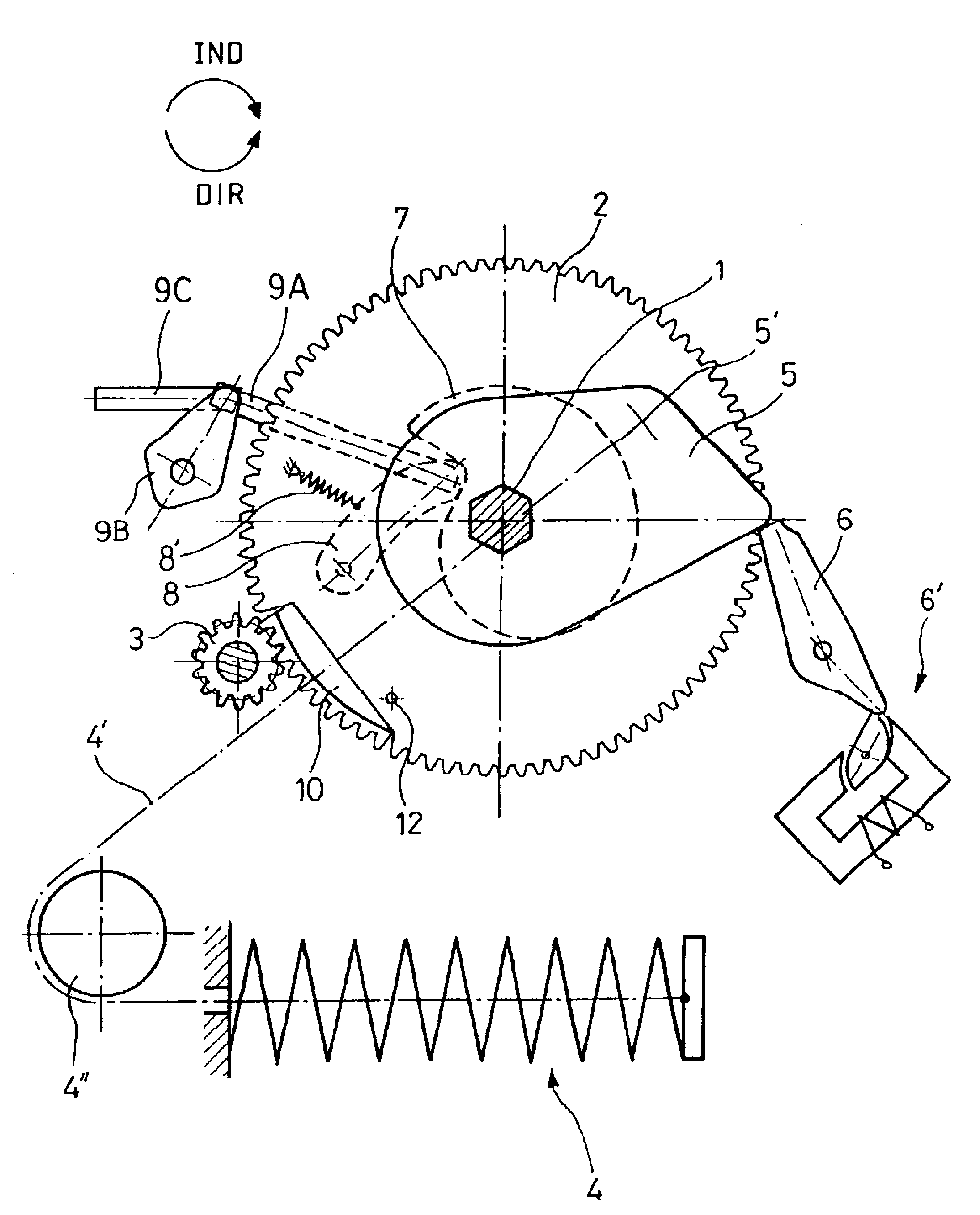
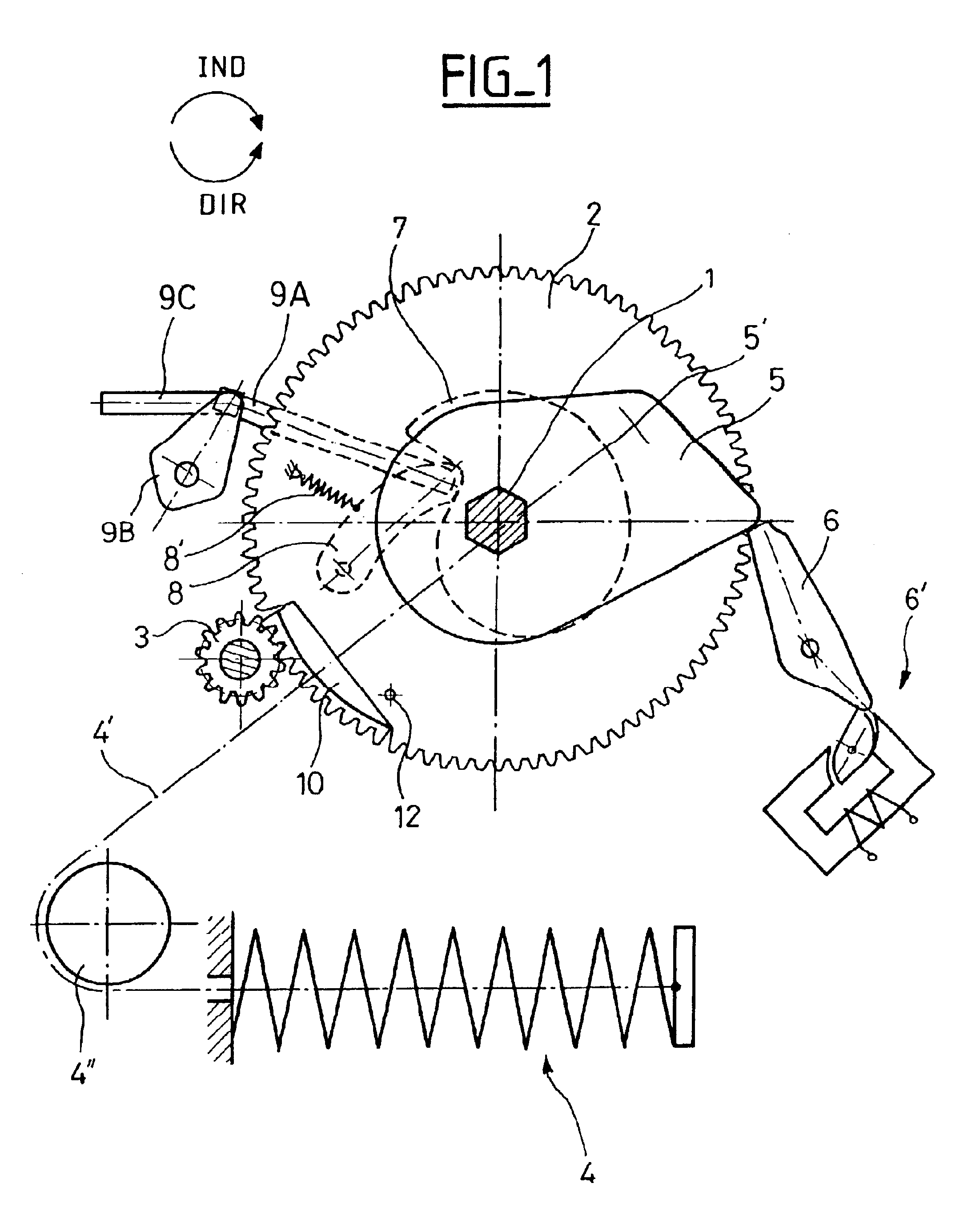
As shown in FIG. 1, the re-loading system for re-loading the mechanical control mechanism of the invention includes an engagement shaft 1, a large-diameter toothed wheel 2 mounted on said engagement shaft, and a drive motor (not shown) coupled to the toothed wheel 2 via a cog wheel 3. The moving contact of the circuit-breaker is coupled to the engagement shaft, in particular via a main shaft that is known per se and not shown.

The engagement spring 4 serves to drive the engagement shaft 1 to cause the circuit-breaker to close. The spring 4 has a first end connected to a first cam 5 which is secured to the end of the engagement shaft 1, and a second end coupled to the frame of the control mechanism. More particularly, the first end of the spring 4 is coupled to an anchor point 5' on the first cam via a cable 4' or a chain passing over a deflector pulley 4". The anchor point 5' on the first cam 5 is eccentric relative to the engagement shaft 1, so that, when the engagement shaft is in ...


PUM


Abstract

The spring-loaded mechanical control mechanism for a circuit-breaker in a high-voltage or medium-voltage grid comprises a toothed wheel turned by a spring from a first angular position to a second angular position, and a cog wheel co-operating with the toothed wheel to displace it from the second angular position to the first angular position so as to tension said spring. The toothed wheel has a peripheral set of teeth including a retractable segment on which at least four teeth are spaced apart from one another at a constant pitch identical to the pitch of the primary teeth.

Description

The invention relates to a spring-loaded mechanical control mechanism for a circuit-breaker in a high-voltage or medium-voltage grid, said control mechanism comprising a toothed wheel turned by a spring from a first angular position to a second angular position, and a cog wheel co-operating with the toothed wheel to displace it from the second angular position to the first angular position so as to tension said spring, said toothed wheel having a peripheral set of teeth constituted firstly by a primary set of teeth secured to the wheel, and secondly by a portion of a set of teeth in the form of a retractable toothed segment, said primary set of teeth having a constant pitch.A "circuit-breaker in a high-voltage or medium-voltage grid" is to be understood as covering any interrupting switchgear designed for an electricity grid whose operating voltage is greater than 1 kV.The invention may firstly be applied to a mechanical control mechanism in which the toothed wheel is secured to a s...

Claims


Application Information

Patent Timeline
Patent Type & Authority Patents(United States)
IPC IPC(8): H01H3/30H01H3/00
CPCH01H3/3005Y10T74/19949H01H2003/3063
Inventor ALLMEN, PETER VON
Owner ALSTOM TECH LTD
Why Eureka
Try Eureka