Eureka AIR delivers breakthrough ideas for toughest innovation challenges, trusted by R&D personnel around the world.

Position measurement system and method

a technology of position measurement and measurement method, applied in the direction of printing mechanism, spacing mechanism, printing, etc., can solve the problem of large drop placement error, achieve the effect of reducing the distance between the codestrip and the printhead, avoiding cluttering the generally crowded print zone area, and accurately determining the position of the printhead

Inactive Publication Date: 2004-10-26
HEWLETT PACKARD DEV CO LP
View PDF1 Cites 6 Cited by
  • Summary
  • Abstract
  • Description
  • Claims
  • Application Information

AI Technical Summary

Benefits of technology

By measuring the position of the carriage or printhead relative to the scan axis relative to more than one codestrip, position and orientation information relating to the carriage or printhead may be determined. Thus, the position of a precise location or part of the printhead or carriage may be known relative to the scan axis, for example. Thus, in the event that the orientation of the printhead or carriage alters as it crosses the scan axis, for example due to imperfections associated with the straightness of the scan axis, this may be compensated for. This may be achieved by changing the timing of the firing of the nozzles of the printhead. This technique may help to reduce drop placement errors in the ejected nozzles. In this manner, print defects may be reduced.
In one embodiment of the present invention, two codestrips are located spaced apart in the Y axis (the media feed direction), each at a relatively large distance from the printhead. This offers the advantage of avoiding cluttering the generally crowded print zone area with a codestrip. At the same time, by generating an averaged or virtual position of a printhead of the printer, from the two codestrips, the position of the printhead may be accurately determined, even if in the carriage is subject to changes in orientation whilst traversing the scan axis. Conventionally, designers of such systems have attempted to reduce the distance between the codestrip and the printheads. This is because the greater the distance that separates a single codestrip and the printheads, the greater may be the difference in measured and actual position of the printheads when the carriage orientation changes. Consequently, the greater the drop placement error may be. Therefore, the placement of a single codestrip has traditionally been made as close as practicable to the printheads. Thus, it has been a trade off between accepting a degree of drop placement error and design cost. Here the design cost may be in terms of improving the quality of the scan axis in order to reduce imperfections in its straightness for example, and / or attempting to design the print zone to permit the codestrip to be located as close as possible to the prinheads.
In certain embodiments of the invention, one codestrip is located on either side, in the Y axis direction, of the printhead(s). The distance separating each codestrip from the printhead(s) in the Y axis is the same. In this manner, the virtual position signal for the printhead(s) may be a simple average of the signals derived from the two codestrips. This gives rise to the advantage of requiring only a simple computation to determine accurately the position of, for example, the centre of the printhead(s) in the Y axis.
In other embodiments of the invention, the distances separating each codestrip from the printhead(s) may be different. In such embodiments, the virtual position signal for the printhead(s) may be a weighted average of the signals derived from the two codestrips; with the weighting being dependent upon the relative distances that the two codestrips are separated from printheads. This gives rise to the advantage of giving design flexibility to the design of the hard copy device, allowing the relatively unconstrained placement of the codestrips relative to the print zone. It will thus be understood that the average of the first and second carriage position information, be this a weighted, simple or other form of average, may be viewed as a composite of the first and second carriage position information.
In other embodiments of the invention, more than one virtual position signal may be generated from the two codestrips. These may each have a different weighting of the two signals generated from the two codestrips. Unlike single codestrip systems, this gives rise to the advantage of being able to determine the position along the scan axis of two or more points or areas of the carriage or printhead(s) at the same time, where those points occupy different locations in the in the media feed direction. In the case where large printheads are used this may be especially beneficial since even a small rotation of large printhead may cause appreciably different drop placement positions between nozzles in different positions in the printhead(s); and thus appreciable drop placement errors. In this manner, according to such embodiments, the firing of different groups of nozzles or indeed individual nozzles may be independently controlled in dependence upon their detected positions.

Problems solved by technology

Consequently, the greater the drop placement error may be.
Thus, it has been a trade off between accepting a degree of drop placement error and design cost.

Method used


Image

  • Position measurement system and method
  • Position measurement system and method
  • Position measurement system and method

Examples


first embodiment

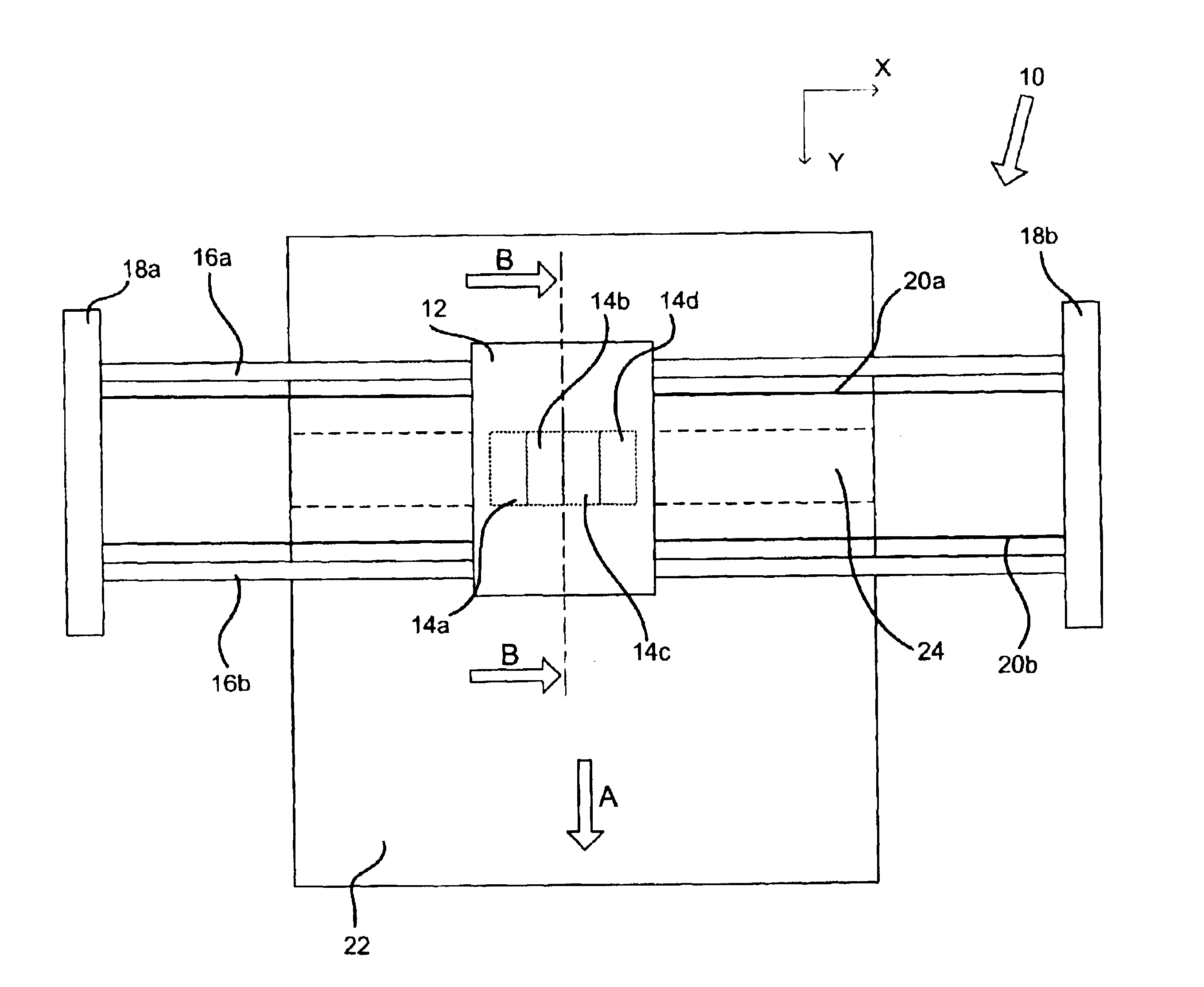
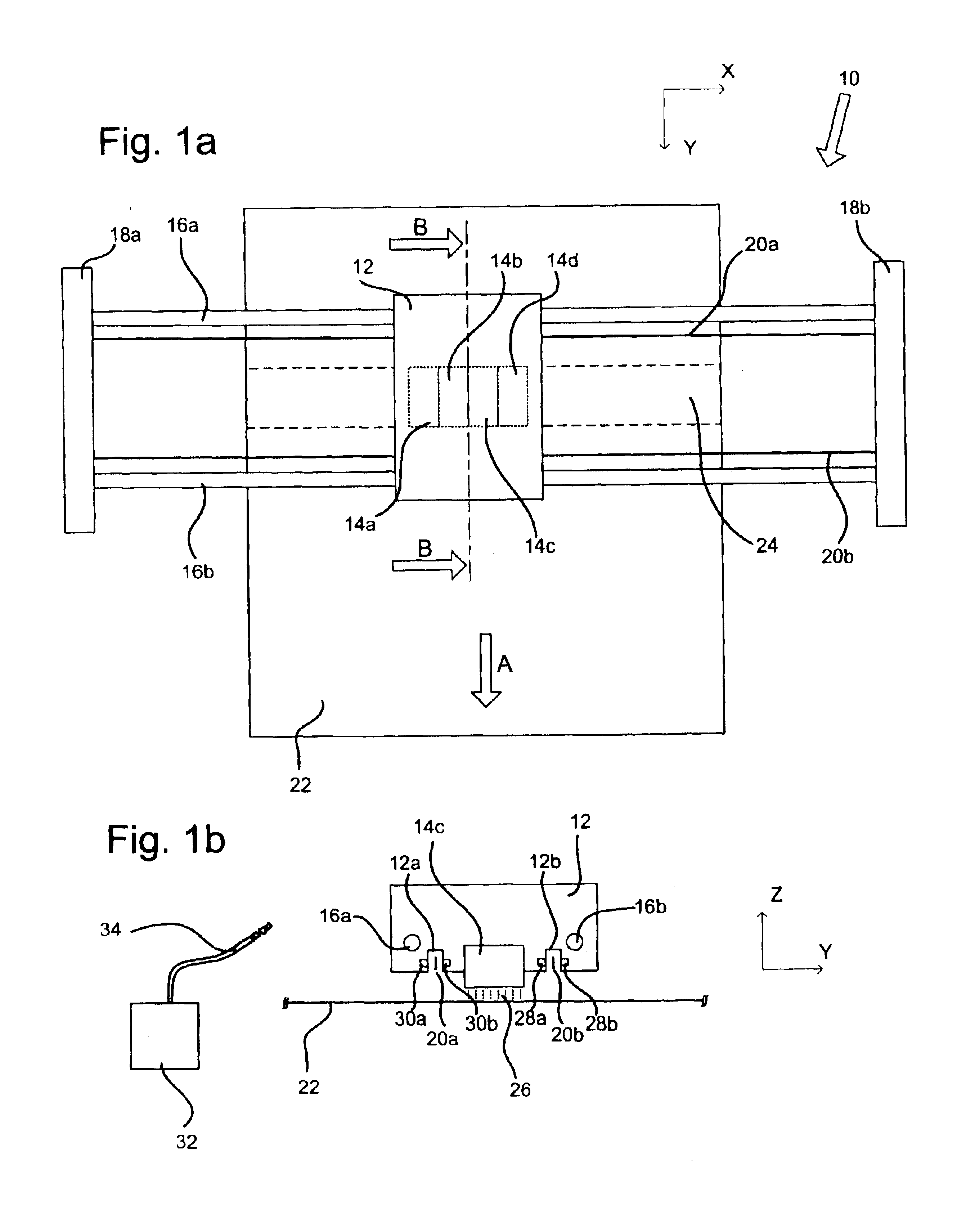
FIG. 1a schematically illustrates an inkjet printing mechanism according to a first embodiment of the invention in plan view. In the present example, the inkjet printing mechanism is large format inkjet printer 10, which is suitable for printing conventional engineering and architectural drawings, as well as high quality poster-sized images.

As can be seen from the figure, the printer 10 has a chassis, here represented by two parallel plates 18a and 18b. Two carriage guide rods 16a and 16b are supported between the plates 18a and 18b. The two guide rods 16a and 16b lie parallel to one another and are aligned with the scanning axis of the printer. This is parallel to the X axis in the figure. The two guide rods 16a and 16b are arranged to support an inkjet carriage 12. The carriage 12 is arranged to be driven back and forth in a conventional manner along the scanning axis, between the plates 18a and 18b and in so doing to traverse the print zone 24 of the printer. In the present embod...

second embodiment

The second embodiment of the present invention generally employs the same apparatus and generally operates in the same manner as described with reference to the first embodiment. Therefore, similar apparatus and methods of operation will not be described further. Additionally, similar components are illustrated and numbered in the same manner as is the case in the earlier embodiment.

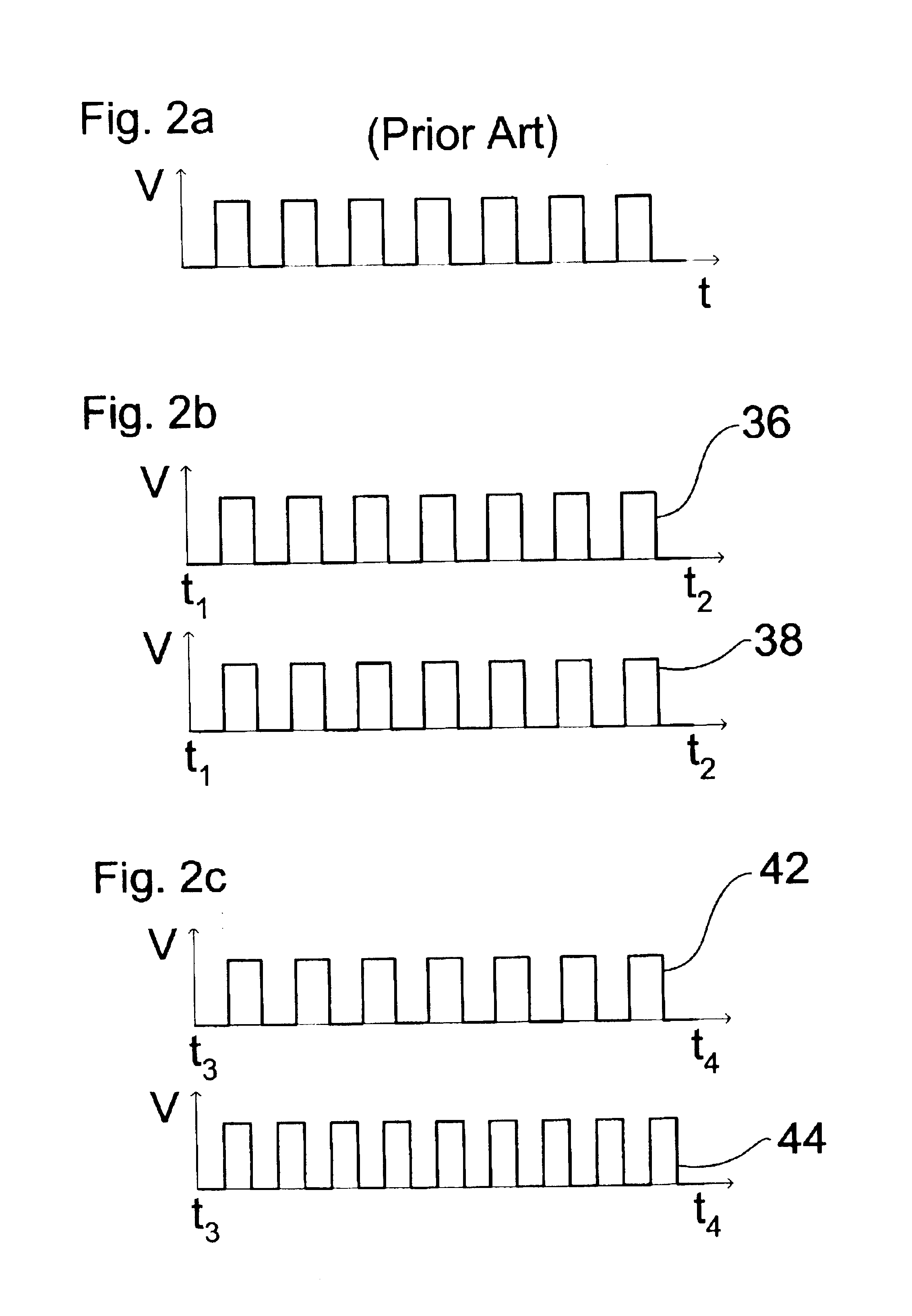
In the second embodiment of the invention, instead of generating a single virtual carriage position signal from the carriage position signals output by the two sensors 28 and 30, multiple virtual carriage position signals are generated. In this way different weighted averages of the carriage position signals output by the two sensors 28 and 30 may be generated and used to determine the firing timing of different groups of ink ejection nozzles in the printheads.

Referring to FIG. 4a, this embodiment will now be described. FIG. 4a schematically illustrates how a given point on the printer carriage 12 is dis...


PUM


Abstract

A hard copy device having a carriage arranged to support a printhead and to reciprocate across a scan axis, the device being arranged to determine the position of at least a part of the printhead along the scan axis, compensating for carriage rotation about the an axis orthogonal to the scan axis, by interpolating or extrapolating from carriage position information derived from first and second codestrips traversing the scan axis and spaced apart in a direction orthogonal to the scan axis.

Description

FIELD OF THE INVENTIONThe present invention relates generally to a position measurement system, particularly, although not exclusively, to a method and apparatus for determining the position of scanning printer carriages in inkjet printer devices.BACKGROUND OF THE INVENTIONInkjet printer devices generally incorporate one or more inkjet cartridges, often called "pens", which shoot drops of ink onto a page or sheet of print media. For instance, two earlier thermal ink ejection mechanisms are shown in U.S. Pat. Nos. 5,278,584 and 4,683,481, both assigned to the present assignee, Hewlett-Packard Company. The pens are usually mounted on a carriage, which is arranged to scan across a slider rod that traverses a print zone, in which a sheet of print media may be located. As the carriage traverses the print zone, the pens print a series of individual drops of ink on the print media forming a band or "swath" of an image, such as a picture, chart or text. The print media is subsequently moved...

Claims


Application Information

Patent Timeline
IPC IPC(8): B41J19/20
CPCB41J19/202
Inventor BRUGU, JOAQUIMHIERRO, LLUISGARCIA, JESUSRIUS, MARTI
Owner HEWLETT PACKARD DEV CO LP
Why Eureka
Eureka Blog
Learn More