Throttle-valve assembly

Inactive Publication Date: 2004-08-10
CONTINENTAL AUTOMOTIVE GMBH
View PDF11 Cites 10 Cited by
  • Summary
  • Abstract
  • Description
  • Claims
  • Application Information

AI Technical Summary

Benefits of technology

The metal insert is advantageously constructed so as to hold the bearings of the throttle-valve shaft. As a result, the bearings are integrated in the mechanical stability of the metal insert. This arrangement of the bearings enables the throttle-valve shaft to be mounted in a particularly stable manner in the metal insert.
A position detection device is advantageously provided for the throttle-valve shaft, a holder being integrated in the metal insert for the position detection device. In this case, the mechanical stability of the metal insert ensures that the position detection device is particularly securely held in the housing of the throttle-valve assembly. At the same time, the position detection device can additionally be pre-adjusted relative to the throttle-valve shaft via the holder provided in the metal insert, as a result of which the position detection device requires only a particularly small amount of adjustment. In this case, the position detection device can be put into place even at the point at which the metal insert is integrated in the housing.
The actuator is advantageously to be arranged on a base plate, the base plate being constructed as a single piece with the metal insert. By this means, heat arising during operation of the actuator can be conducted away to the metal insert via the base plate, with sufficient cooling of the metal insert being reliably ensured by the gaseous medium passing through the throttle opening.
The advantages obtained with the invention reside, in particular, in the fact that a characteristic curve for a throttle-valve assembly can be obtained by a special shaping of the throttle opening in the region of movement of the throttle valve and not by a change in the shape of the throttle valve and / or arrangement of the throttle-valve shaft, said characteristic curve covering a range which has previously not been achieved with known throttle-valve assemblies. This range of the characteristic curves for a throttle-valve assembly that has been acquired by the invention is advantageous in particular in the case of throttle valves having a particularly large diameter, so that the latter, in spite of their size, reliably ensure a particularly finely graduated control of the power of the internal combustion engine.

Problems solved by technology

Housings of throttle-valve assemblies which are manufactured from metal, for example, aluminum, may have particularly low tolerances.
However, metal housings of throttle-valve assemblies have the disadvantage that, after the housing has been produced, for example by die-casting, complicated re-machining of the housing is required.
This may prove disadvantageous if the throttle valve and the throttle opening have a particularly large diameter, for example 90 mm or more.
This is because, from a certain opening angle of the throttle valve, the mass of flow medium passing through the throttle opening only changes to a particularly small extent per unit of time, in particular at a particularly large diameter of the throttle valve, when the position of the throttle valve changes, which means that a finely graduated control of the power of the motor vehicle is no longer possible from a certain opening angle of the throttle valve.
As a result, sealing problems between the approximately straight cylinder section in the region of movement of the throttle valve and the spherical-cap section do not occur.
Moreover, unevennesses in the boundary region between the approximately straight cylinder section in the region of movement of the throttle valve and the spherical-cap section could result in swirling of the gaseous medium passing through the throttle opening during operation of the throttle-valve assembly, which could have a negative effect on the characteristic curve of the throttle valve.

Method used


Image

  • Throttle-valve assembly
  • Throttle-valve assembly
  • Throttle-valve assembly

Examples


Embodiment Construction

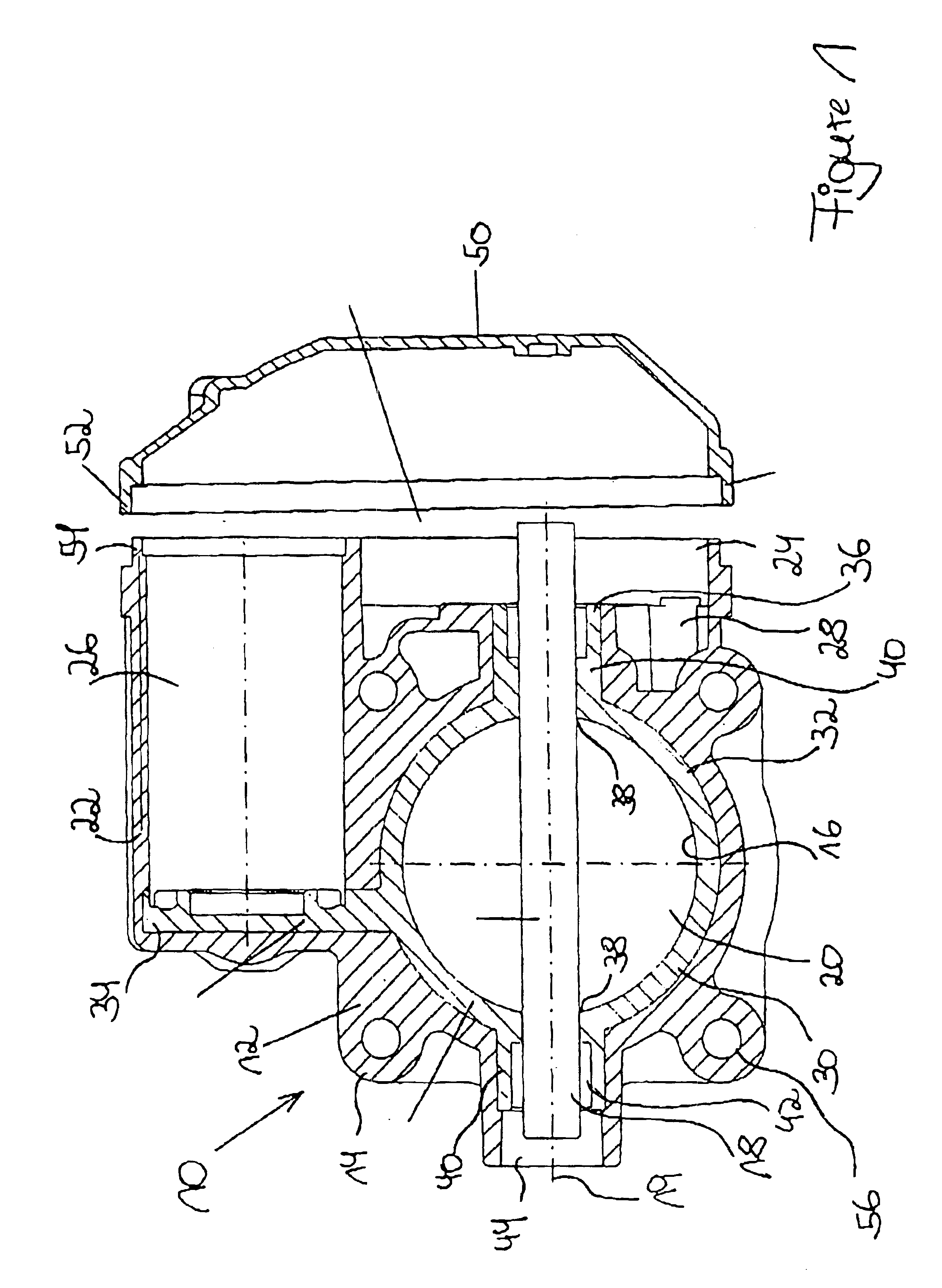
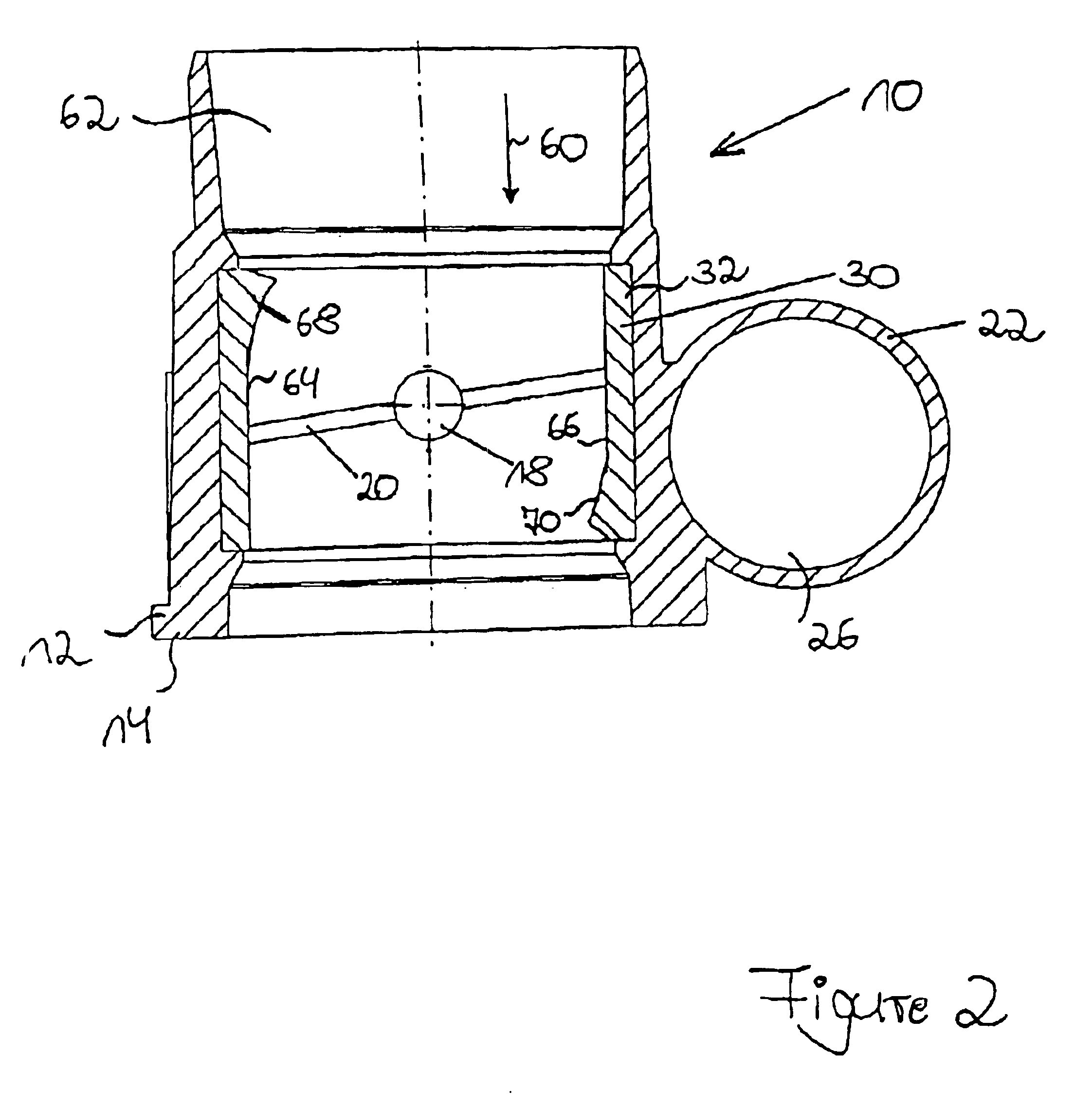
The throttle-valve assembly 10 according to FIG. 1 is used to feed air or a fuel / air mixture to a consumer (not illustrated), for example an injection device of a motor vehicle (likewise not illustrated), it being possible to control the quantity of fresh air to be fed to the consumer by means of the throttle-valve assembly 10. For this purpose, the throttle-valve assembly 10 has a housing 12 which is manufactured predominantly from plastic 14 and has been produced by injection molding. As an alternative, however, the housing 12 can also be manufactured entirely from metal, in particular aluminum. The housing 12 has a throttle opening 16 via which the air or a fuel / air mixture can be fed to the consumer (not illustrated). To allow the volume of fresh gas to be fed in to be adjusted, a throttle valve 20 is arranged on a throttle-valve shaft 18. Rotating the throttle-valve shaft 18 about its axis of rotation 19 simultaneously pivots the throttle valve 20 arranged on the throttle-valve...


PUM


Abstract

A throttle-valve assembly (10) having a housing (12), which has a continuous throttle opening (16) through which a gaseous medium (62) can flow in a main flow direction (60), in which a throttle valve (20) fastened pivotably on a throttle-valve shaft (18) is arranged in the throttle opening (16), and the throttle-valve shaft (18) can be pivoted by an actuator (26) arranged in the housing (12), in which, starting from the axis of rotation (19) of the throttle-valve shaft (18) downstream along the main flow direction (60) of the gaseous medium (62), the throttle opening (16) has an approximately straight cylinder section (64) with a height H1 and a radius RZ and in which a spherical-cap section (68) adjoins the approximately straight cylinder section (64). To reliably ensure a finely graduated control of the gaseous medium (62) passing through the throttle opening (16) during operation of the throttle-valve assembly (10), the spherical-cap section (68) has a central point (80) which, starting from the axis of rotation (19) of the throttle-valve shaft (18) downstream along the main flow direction (60) of the gaseous medium (62), is displaced by a distance H2, with the spherical-cap section (68) having a radius RK which is approximately determined by the following equation:

Description

FIELD AND BACKGROUND OF THE INVENTIONThe invention relates to a throttle-valve assembly having a housing, which has a continuous throttle opening through which a gaseous medium can flow in a main flow direction, in which a throttle valve fastened pivotably on a throttle-valve shaft is arranged in the throttle opening, in which the throttle-valve shaft can be pivoted by an actuator arranged in the housing, in which, starting from the axis of rotation of the throttle-valve shaft downstream along the main flow direction of the gaseous medium, the throttle opening has an approximately straight cylinder section with a height H.sub.1 and a radius R.sub.Z and in which a spherical-cap section adjoins the approximately straight cylinder section.To control the quantity of fresh gas for a motor vehicle, use is generally made of throttle-valve assemblies. Throttle-valve assemblies comprise a housing having a throttle opening and a throttle element arranged in the throttle opening. The throttle ...

Claims


Application Information

Patent Timeline
IPC IPC(8): F02D9/10F02D9/08F16K27/02F16K1/22
CPCF02D9/10F02D9/104F02D9/1065F16K1/22F16K27/0218B29L2031/7506F02D9/107F05C2201/021F02M19/00
Inventor KOHLEN, PETER
Owner CONTINENTAL AUTOMOTIVE GMBH
Why Eureka
Try Eureka